Difference between revisions of "Hrrl pos jul2012 shieldings"
Jump to navigation
Jump to search
| (2 intermediate revisions by the same user not shown) | |||
| Line 1: | Line 1: | ||
= Effects of Iron shielding on the dipole = | = Effects of Iron shielding on the dipole = | ||
| + | |||
| + | |||
| + | Shieldings: | ||
[[File:hrrl_pos_jul2012_shielding_1.jpg | 300 px]] [[File:hrrl_pos_jul2012_shielding_2.jpg | 300 px]] | [[File:hrrl_pos_jul2012_shielding_1.jpg | 300 px]] [[File:hrrl_pos_jul2012_shielding_2.jpg | 300 px]] | ||
| Line 7: | Line 10: | ||
[[File:hrrl_pos_jul2012_shielding_9.jpg | 300 px]] [[File:hrrl_pos_jul2012_shielding_10.jpg | 300 px]] | [[File:hrrl_pos_jul2012_shielding_9.jpg | 300 px]] [[File:hrrl_pos_jul2012_shielding_10.jpg | 300 px]] | ||
[[File:hrrl_pos_jul2012_shielding_11.jpg | 300 px]] [[File:hrrl_pos_jul2012_shielding_12.jpg | 300 px]] | [[File:hrrl_pos_jul2012_shielding_11.jpg | 300 px]] [[File:hrrl_pos_jul2012_shielding_12.jpg | 300 px]] | ||
| + | [[File:hrrl_pos_jul2012_shielding_13.jpg | 300 px]] [[File:hrrl_pos_jul2012_shielding_14.jpg | 300 px]] | ||
| + | [[File:hrrl_pos_jul2012_shielding_15.jpg | 300 px]] | ||
| + | |||
| + | |||
| + | |||
| + | |||
| + | |||
| + | 2" thick brick with 2" diameter hole placed at the exit of the vacuum window, then NaI detectors were placed next to the brick. The distance between NaI detector and the edge of the 6-way cross is | ||
| + | |||
| + | Detector Left: | ||
| + | |||
| + | |||
| + | [[File:hrrl_pos_jul2012_setup_DL_1.jpg | 300 px]] [[File:hrrl_pos_jul2012_setup_DL_2.jpg | 300 px]] | ||
| + | [[File:hrrl_pos_jul2012_setup_DL_3.jpg | 300 px]] [[File:hrrl_pos_jul2012_setup_DL_4.jpg | 300 px]] | ||
| + | [[File:hrrl_pos_jul2012_setup_DL_5.jpg | 300 px]] [[File:hrrl_pos_jul2012_setup_DL_6.jpg | 300 px]] | ||
| + | [[File:hrrl_pos_jul2012_setup_DL_7.jpg | 300 px]] [[File:hrrl_pos_jul2012_setup_DL_8.jpg | 300 px]] | ||
| + | |||
| + | |||
| + | |||
| + | |||
| + | |||
| + | |||
| + | Detector Right: | ||
| + | |||
| + | [[File:hrrl_pos_jul2012_setup_DR_1.jpg | 300 px]] [[File:hrrl_pos_jul2012_setup_DR_2.jpg | 300 px]] | ||
| + | |||
| + | |||
| + | There is 2" thick Pb brick with 2" diameter hole to act as collimator. | ||
| + | |||
| + | [[File:hrrl_pos_jul2012_setup_Collimator_1.jpg | 300 px]] [[File:hrrl_pos_jul2012_setup_Collimator_2.jpg | 300 px]] | ||
| + | [[File:hrrl_pos_jul2012_setup_Collimator_3.jpg | 300 px]] [[File:hrrl_pos_jul2012_setup_Collimator_4.jpg | 300 px]] | ||
| + | |||
| + | |||
| + | |||
| + | |||
| + | |||
Dipole mappings in the center region: https://wiki.iac.isu.edu/index.php/Kiwi_Dipole_Mappings#Rotation | Dipole mappings in the center region: https://wiki.iac.isu.edu/index.php/Kiwi_Dipole_Mappings#Rotation | ||
Latest revision as of 23:23, 31 July 2012
Effects of Iron shielding on the dipole
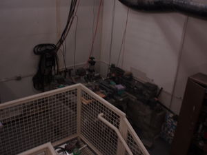
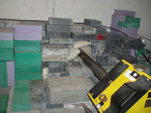
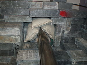
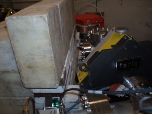
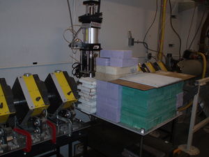
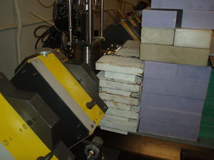
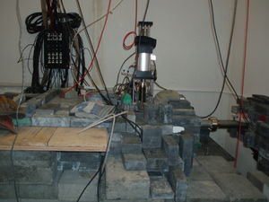
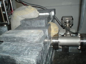
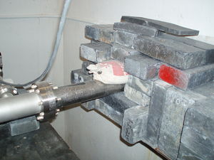
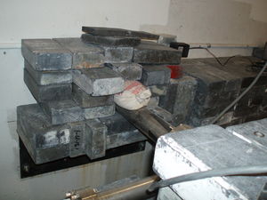
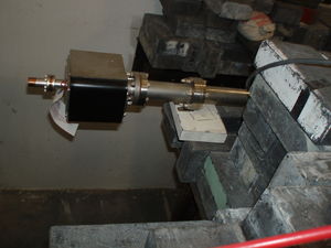
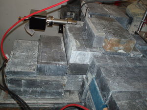
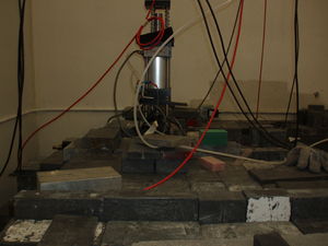
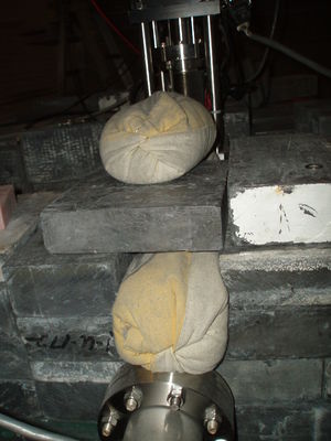
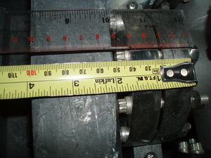
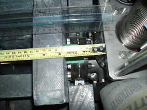
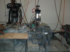
Shieldings:
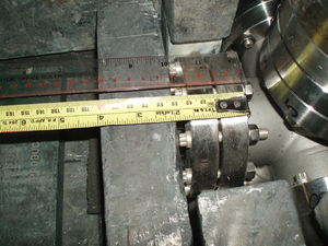
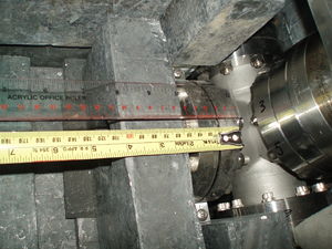
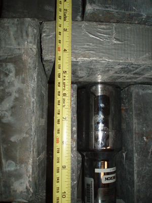
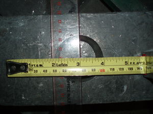
2" thick brick with 2" diameter hole placed at the exit of the vacuum window, then NaI detectors were placed next to the brick. The distance between NaI detector and the edge of the 6-way cross is
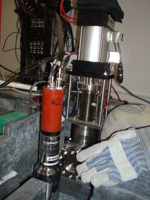
Detector Left:
Detector Right:
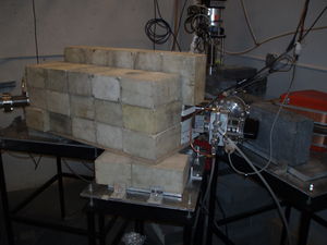
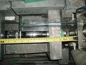
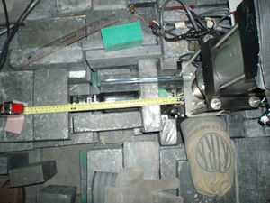
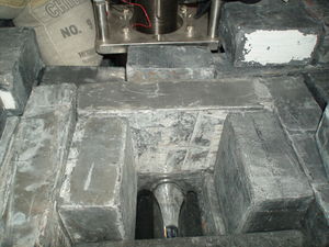
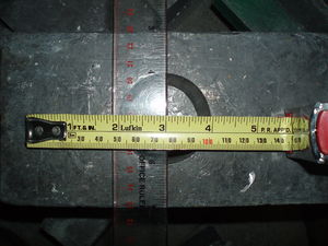
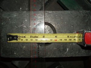
There is 2" thick Pb brick with 2" diameter hole to act as collimator.
Dipole mappings in the center region: https://wiki.iac.isu.edu/index.php/Kiwi_Dipole_Mappings#Rotation
Magnetic field at the edge (the side has shielding next to it) of the dipole was measured using Dr. Dale's probe. Measurement were done 3 points, they located at the center and two sides.
            B-field (Gauss)
           A         B        C
6  Amps   -15      -45        -35
15 Amps   -47.5    -113       -70.5
21 Amps   -55      -156       -79
