Difference between revisions of "Beam Test Jul 19 2012"
Jump to navigation
Jump to search
(Created page with ' Tune up 10 MeV on the zero line. Insert Tungsten target and do a dipole scan to determine relative yield as a function of energy. Attempt to measure relative yield using inte…') |
|||
| (25 intermediate revisions by 2 users not shown) | |||
| Line 1: | Line 1: | ||
| − | |||
Tune up 10 MeV on the zero line. | Tune up 10 MeV on the zero line. | ||
| Line 5: | Line 4: | ||
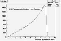
[[File:HRRL_10MeVePdist_71812.png || 200 px]] | [[File:HRRL_10MeVePdist_71812.png || 200 px]] | ||
| + | |||
| + | = 10 MeV Tune = | ||
| + | |||
| + | {| border="1" | ||
| + | | Energy Switch || Out (High En) | ||
| + | |- | ||
| + | | Solenoid 1 || 6.2 A | ||
| + | |- | ||
| + | | Solenoid 2 || 3.3 A | ||
| + | |- | ||
| + | | Gun Hor || -0.2 A | ||
| + | |- | ||
| + | | Gun Ver || 0 A | ||
| + | |- | ||
| + | |Output Hor || -0.3 A | ||
| + | |- | ||
| + | | Output Ver || 0 A | ||
| + | |- | ||
| + | | Rep Rate || 8 | ||
| + | |- | ||
| + | | Gun HV || 10 (Knob Setting) | ||
| + | |- | ||
| + | | Gun Grid Voltage || 10 (Knob Setting) | ||
| + | |- | ||
| + | | RF frequency ||2856.320 MHz | ||
| + | |- | ||
| + | | Modulator HV Power Supply || 4.28 (Knob Setting) | ||
| + | |- | ||
| + | | RF macro Pulse Length (FWHM) || 300 ns | ||
| + | |- | ||
| + | |Q1 (A)|| -3.7 | ||
| + | |- | ||
| + | |Q2 (A)|| -5.5 | ||
| + | |- | ||
| + | |Q3 (A)|| +0.6 | ||
| + | |- | ||
| + | |} | ||
| + | |||
| + | = Counting single pulse = | ||
| + | |||
| + | |||
| + | == Settings == | ||
| + | |||
| + | |||
| + | Gun Grid Voltage knob setting: 2.85 | ||
| + | |||
| + | |||
| + | {| border="1" | ||
| + | | Energy Switch || Out (High En) | ||
| + | |- | ||
| + | | Solenoid 1 || 6.2 A | ||
| + | |- | ||
| + | | Solenoid 2 || 3.3 A | ||
| + | |- | ||
| + | | Gun Hor || -0.2 A | ||
| + | |- | ||
| + | | Gun Ver || 0 A | ||
| + | |- | ||
| + | |Output Hor || -0.3 A | ||
| + | |- | ||
| + | | Output Ver || 0 A | ||
| + | |- | ||
| + | | Rep Rate || 8 | ||
| + | |- | ||
| + | | Gun HV || 10 (Knob Setting) | ||
| + | |- | ||
| + | | Gun Grid Voltage || 2.85 (Knob Setting) | ||
| + | |- | ||
| + | | RF frequency ||2856.320 MHz | ||
| + | |- | ||
| + | | Modulator HV Power Supply || 4.28 (Knob Setting) | ||
| + | |- | ||
| + | | RF macro Pulse Length (FWHM) || 300 ns | ||
| + | |- | ||
| + | |Q1 (A)|| -3.7 | ||
| + | |- | ||
| + | |Q2 (A)|| -5.5 | ||
| + | |- | ||
| + | |Q3 (A)|| +0.6 | ||
| + | |- | ||
| + | |} | ||
| + | |||
| + | |||
| + | {| border="1" | ||
| + | | W1 || Sweeping magnet || D1 (A) || D2 (A) || Mode|| Jaw width (cm) || Sintilator HV || q4 (A) || q5 (A) || q6 (A) || q7 (A) || q8 (A)|| q9 (A) || q10 (A) || conditions | ||
| + | |- | ||
| + | |||
| + | | in || out || 4.2 || 4.2 || 2 MeV e- || 1 || 1219 V ||+1 || -0 || -0.1|| -0 || +1.3 || +0.5 || -0 || D1 & D2 set to 2 MeV e- | ||
| + | |||
| + | |||
| + | |} | ||
| + | |||
| + | Optimization of the magnets in positron mode: | ||
| + | |||
| + | q4 q5 q6 q7 q8 q9 q10 counts / time (s) Rate (Hz) | ||
| + | +1.0 -0.0 -0.1 +4.0 +1.0 +0.5 -0.0 740 / 201.4 3.67 | ||
| + | +1.0 -0.0 -0.1 +4.5 +1.0 +0.5 -0.0 611 / 149.9 4.08 | ||
| + | +1.0 -0.0 -0.1 +5.0 +1.0 +0.5 -0.0 360 / 100 3.6 | ||
| + | +1.0 -0.0 -0.1 +4.7 +1.0 +0.5 -0.0 309 / 80.1 3.86 | ||
| + | +1.0 -0.0 -0.1 +4.3 +1.0 +0.5 -0.0 220 / 60.1 3.66 | ||
| + | +1.0 -0.0 -0.1 +4.5 +1.0 +0.5 -0.0 202 / 50.1 4.03 | ||
| + | +2.0 -0.0 -0.1 +4.5 +1.0 +0.5 -0.0 194 / 49.2 3.94 | ||
| + | |||
| + | +0.0 -0.0 -0.1 +4.5 +1.0 +0.5 -0.0 223 / 50.2 4.44 | ||
| + | |||
| + | -0.5 -0.0 -0.1 +4.5 +1.0 +0.5 -0.0 192 / 50 3.84 | ||
| + | -0.2 -0.0 -0.1 +4.5 +1.0 +0.5 -0.0 242 / 60 4.03 | ||
| + | +0.5 -0.0 -0.1 +4.5 +1.0 +0.5 -0.0 394 / 90.2 4.37 | ||
| + | +0.2 -0.0 -0.1 +4.5 +1.0 +0.5 -0.0 272 / 69.9 3.89 | ||
| + | |||
| + | +0.0 -0.0 -0.1 +4.5 +1.0 +0.5 -0.0 472 / 99.9 4.72 | ||
| + | |||
| + | +0.0 -0.0 -0.0 +0.0 +0.0 +0.0 -0.0 133 / 50.2 2.65 | ||
| + | +0.0 -0.0 -0.0 +4.5 +0.0 +0.0 -0.0 167 / 50.0 3.34 | ||
| + | |||
| + | |||
| + | |||
| + | -0.0 +0.0 -0.1 +4.5 -0.0 -0.0 +0.0 193 / 60.0 3.22 | ||
| + | -0.0 +0.0 +0.0 +4.5 -0.0 -0.0 +0.0 148 / 50.1 2.95 | ||
| + | -0.0 +0.0 +0.1 +4.5 -0.0 -0.0 +0.0 162 / 50.0 3.24 | ||
| + | -0.0 +0.0 +0.2 +4.5 -0.0 -0.0 +0.0 179 / 50.0 3.58 | ||
| + | -0.0 +0.0 +0.3 +4.5 -0.0 -0.0 +0.0 185 / 49.9 3.71 | ||
| + | -0.0 +0.0 +0.5 +4.5 -0.0 -0.0 +0.0 184 / 49.9 3.69 | ||
| + | -0.0 +0.0 +0.7 +4.5 -0.0 -0.0 +0.0 154 / 50.1 3.07 | ||
| + | |||
| + | -0.0 +0.0 +0.4 +4.5 -1.0 -0.0 +0.0 208 / 50.0 4.16 | ||
| + | |||
| + | -0.0 +0.5 +0.4 +4.5 -1.0 -0.0 +0.0 911 / 180.1 5.06 | ||
| + | |||
| + | Dipole test | ||
| + | D1 q4 q5 q6 q7 q8 q9 q10 counts / time (s) Rate (Hz) | ||
| + | 0 -0.0 +0.5 +0.4 +4.5 -1.0 -0.0 +0.0 423 / 109.9 3.85 | ||
| + | |||
| + | = Daq Runs = | ||
| + | |||
| + | Detector left (Det2) is at CH6. | ||
| + | Detector right (Det3) is at CH5. | ||
| + | |||
| + | Run# Reprate T1 T2 Start Time Stop Time Int Rate | ||
| + | 3593 100 in in 13:47:22 pm 14:23:46 pm 1.46 | ||
| + | 3594 100 in out 14:24:39 14:46:44 2.78 | ||
| + | |||
| + | |||
| + | ==Source Calibration RUns== | ||
| + | |||
| + | |||
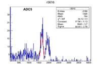
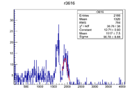
| + | Run 3616 Co-60 source HV NaI Beam Right = 1060 signal in ADC5 | ||
| + | |||
| + | [[File:r3616_Co60_NaIBR_1060VoltsADC5.png | 200 px]] | ||
| + | [[File:r3616_Co60a_NaIBR_1060VoltsADC5.png | 200 px]] | ||
| + | |||
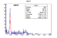
| + | Run 3617 Na-22 source HV NaI Beam Right = 1060 signal in ADC5 | ||
| + | |||
| + | [[File:r3617_Na22_NaIBR_1060VoltsADC5.png | 200 px]] | ||
| + | |||
| + | |||
| + | Run 3618 Co-60 source HV NaI Beam Left = 1080 signal in ADC6 | ||
| + | |||
| + | [[File:r3618_Co60_NaIBR_1080VoltsADC6.png | 200 px]] | ||
| + | [[File:r3618_Co60a_NaIBR_1080VoltsADC6.png | 200 px]] | ||
| + | |||
| + | Run 3619 Na-22 source HV NaI Beam Left = 1080 signal in ADC6 | ||
| + | |||
| + | [[File:r3619_Na22_NaIBR_1080VoltsADC6.png | 200 px]] | ||
Latest revision as of 22:37, 22 July 2012
Tune up 10 MeV on the zero line.
Insert Tungsten target and do a dipole scan to determine relative yield as a function of energy. Attempt to measure relative yield using integral of thick scintillator output for constant current and energy slit setting.
10 MeV Tune
| Energy Switch | Out (High En) |
| Solenoid 1 | 6.2 A |
| Solenoid 2 | 3.3 A |
| Gun Hor | -0.2 A |
| Gun Ver | 0 A |
| Output Hor | -0.3 A |
| Output Ver | 0 A |
| Rep Rate | 8 |
| Gun HV | 10 (Knob Setting) |
| Gun Grid Voltage | 10 (Knob Setting) |
| RF frequency | 2856.320 MHz |
| Modulator HV Power Supply | 4.28 (Knob Setting) |
| RF macro Pulse Length (FWHM) | 300 ns |
| Q1 (A) | -3.7 |
| Q2 (A) | -5.5 |
| Q3 (A) | +0.6 |
Counting single pulse
Settings
Gun Grid Voltage knob setting: 2.85
| Energy Switch | Out (High En) |
| Solenoid 1 | 6.2 A |
| Solenoid 2 | 3.3 A |
| Gun Hor | -0.2 A |
| Gun Ver | 0 A |
| Output Hor | -0.3 A |
| Output Ver | 0 A |
| Rep Rate | 8 |
| Gun HV | 10 (Knob Setting) |
| Gun Grid Voltage | 2.85 (Knob Setting) |
| RF frequency | 2856.320 MHz |
| Modulator HV Power Supply | 4.28 (Knob Setting) |
| RF macro Pulse Length (FWHM) | 300 ns |
| Q1 (A) | -3.7 |
| Q2 (A) | -5.5 |
| Q3 (A) | +0.6 |
| W1 | Sweeping magnet | D1 (A) | D2 (A) | Mode | Jaw width (cm) | Sintilator HV | q4 (A) | q5 (A) | q6 (A) | q7 (A) | q8 (A) | q9 (A) | q10 (A) | conditions |
| in | out | 4.2 | 4.2 | 2 MeV e- | 1 | 1219 V | +1 | -0 | -0.1 | -0 | +1.3 | +0.5 | -0 | D1 & D2 set to 2 MeV e-
|
Optimization of the magnets in positron mode:
q4     q5   q6     q7    q8     q9     q10        counts   /    time (s)    Rate (Hz)
+1.0   -0.0  -0.1   +4.0  +1.0   +0.5   -0.0      740      /    201.4       3.67
+1.0   -0.0  -0.1   +4.5  +1.0   +0.5   -0.0      611      /    149.9       4.08
+1.0   -0.0  -0.1   +5.0  +1.0   +0.5   -0.0      360      /    100         3.6
+1.0   -0.0  -0.1   +4.7  +1.0   +0.5   -0.0      309      /    80.1        3.86
+1.0   -0.0  -0.1   +4.3  +1.0   +0.5   -0.0      220      /    60.1        3.66
+1.0   -0.0  -0.1   +4.5  +1.0   +0.5   -0.0      202      /    50.1        4.03
+2.0   -0.0  -0.1   +4.5  +1.0   +0.5   -0.0      194      /    49.2        3.94
+0.0 -0.0 -0.1 +4.5 +1.0 +0.5 -0.0 223 / 50.2 4.44
-0.5   -0.0  -0.1   +4.5  +1.0   +0.5   -0.0      192      /    50          3.84
-0.2   -0.0  -0.1   +4.5  +1.0   +0.5   -0.0      242      /    60          4.03
+0.5   -0.0  -0.1   +4.5  +1.0   +0.5   -0.0      394      /    90.2        4.37
+0.2   -0.0  -0.1   +4.5  +1.0   +0.5   -0.0      272      /    69.9        3.89
+0.0 -0.0 -0.1 +4.5 +1.0 +0.5 -0.0 472 / 99.9 4.72
+0.0   -0.0  -0.0   +0.0  +0.0   +0.0   -0.0      133      /    50.2        2.65
+0.0   -0.0  -0.0   +4.5  +0.0   +0.0   -0.0      167      /    50.0        3.34
-0.0   +0.0  -0.1   +4.5  -0.0   -0.0   +0.0      193      /    60.0        3.22
-0.0   +0.0  +0.0   +4.5  -0.0   -0.0   +0.0      148      /    50.1        2.95
-0.0   +0.0  +0.1   +4.5  -0.0   -0.0   +0.0      162      /    50.0        3.24
-0.0   +0.0  +0.2   +4.5  -0.0   -0.0   +0.0      179      /    50.0        3.58
-0.0   +0.0  +0.3   +4.5  -0.0   -0.0   +0.0      185      /    49.9        3.71
-0.0   +0.0  +0.5   +4.5  -0.0   -0.0   +0.0      184      /    49.9        3.69
-0.0   +0.0  +0.7   +4.5  -0.0   -0.0   +0.0      154      /    50.1        3.07
-0.0 +0.0 +0.4 +4.5 -1.0 -0.0 +0.0 208 / 50.0 4.16
-0.0 +0.5 +0.4 +4.5 -1.0 -0.0 +0.0 911 / 180.1 5.06
Dipole test
 D1   q4     q5   q6     q7    q8     q9     q10        counts   /    time (s)    Rate (Hz)
 0    -0.0   +0.5  +0.4   +4.5  -1.0   -0.0   +0.0      423      /    109.9       3.85
Daq Runs
Detector left (Det2) is at CH6. Detector right (Det3) is at CH5.
Run#  Reprate  T1  T2   Start Time    Stop Time     Int Rate
3593  100      in  in   13:47:22 pm   14:23:46 pm   1.46
3594  100      in  out  14:24:39      14:46:44      2.78
Source Calibration RUns
Run 3616 Co-60 source HV NaI Beam Right = 1060 signal in ADC5
Run 3617 Na-22 source HV NaI Beam Right = 1060 signal in ADC5
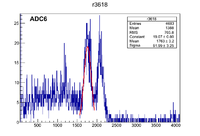
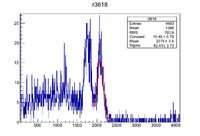
Run 3618 Co-60 source HV NaI Beam Left = 1080 signal in ADC6
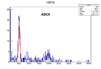
Run 3619 Na-22 source HV NaI Beam Left = 1080 signal in ADC6
