Difference between revisions of "Beam Test Jul 12 2012"
Jump to navigation
Jump to search
| Line 14: | Line 14: | ||
= tune 3 MeV electrons to the 90 degree line= | = tune 3 MeV electrons to the 90 degree line= | ||
| + | |||
| + | {| border="1" | ||
| + | | Energy Switch || Out (High En Range) | ||
| + | |- | ||
| + | | Solenoid 1 || 7.8 A | ||
| + | |- | ||
| + | | Solenoid 2 || 3.9 A | ||
| + | |- | ||
| + | | Gun Hor || 0.1 A | ||
| + | |- | ||
| + | | Gun Ver || 0 A | ||
| + | |- | ||
| + | |Output Hor || 0.3 A | ||
| + | |- | ||
| + | | Output Ver || 0.3 A | ||
| + | |- | ||
| + | | Rep Rate || 6 | ||
| + | |- | ||
| + | | Gun HV || 10 (Knob Setting) | ||
| + | |- | ||
| + | | Gun Grid Voltage || 10(Knob Setting) | ||
| + | |- | ||
| + | | RF frequency ||2856.268 MHz | ||
| + | |- | ||
| + | | Modulator HV Power Supply || 3.66 (Knob Setting) | ||
| + | |- | ||
| + | | RF macro Pulse Length (FWHM) || 200 ns | ||
| + | |- | ||
| + | |Q1 (A)||0 | ||
| + | |- | ||
| + | |Q2 (A)|| 0 | ||
| + | |- | ||
| + | |Q3 (A)|| 0 | ||
| + | |- | ||
| + | |Q4 (A)|| 0 | ||
| + | |- | ||
| + | |Q5 (A)|| 0 | ||
| + | |- | ||
| + | |Q6 (A)|| 0 | ||
| + | |- | ||
| + | |} | ||
==tune to 0 degree line== | ==tune to 0 degree line== | ||
Revision as of 18:18, 12 July 2012
JAI Camera Triggering
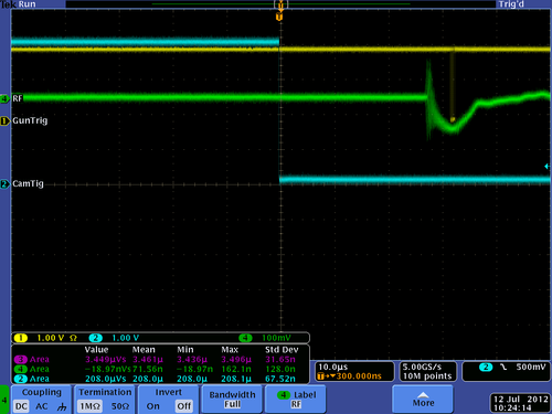
The fall of the TTL pulse triggers the camera.
Camera trigger should arrive at lest 30 micro-second earlier than RF pulse to get the beam image on the OTR.
To do this the first RF pulse trigger should be delayed to trigger the camera for the next RF pulse.
- Note
- RF not would trigger the camera. We added a ground strap to the double shielded BNC cable and covered some unshielded cables with tin foil. This stopped the RF from triggering the camera.
tune 3 MeV electrons to the 90 degree line
| Energy Switch | Out (High En Range) |
| Solenoid 1 | 7.8 A |
| Solenoid 2 | 3.9 A |
| Gun Hor | 0.1 A |
| Gun Ver | 0 A |
| Output Hor | 0.3 A |
| Output Ver | 0.3 A |
| Rep Rate | 6 |
| Gun HV | 10 (Knob Setting) |
| Gun Grid Voltage | 10(Knob Setting) |
| RF frequency | 2856.268 MHz |
| Modulator HV Power Supply | 3.66 (Knob Setting) |
| RF macro Pulse Length (FWHM) | 200 ns |
| Q1 (A) | 0 |
| Q2 (A) | 0 |
| Q3 (A) | 0 |
| Q4 (A) | 0 |
| Q5 (A) | 0 |
| Q6 (A) | 0 |
tune to 0 degree line
Determine the magnet settings needed to optimize the current to FC1.
Take a picture of the beam spot on the YaG and FC1
tune to 45 degree line
Optimize the current to FC2 using Quad 7 and the energy slots
document the settings and current oFC2
tune to 90 degree
Optimize current to FC3 using last 3 quads
Take scope picture
trasmission
Make several measurements using all three FCs to determine the transmission.
Do this by transporting beam to each several times.
