Difference between revisions of "Beam Test Jul 5 2012"
| (10 intermediate revisions by the same user not shown) | |||
| Line 152: | Line 152: | ||
| Peak Current on FC 1 ) || 60 mAmps | | Peak Current on FC 1 ) || 60 mAmps | ||
|- | |- | ||
| − | |||
| − | |||
| − | |||
| − | |||
| − | |||
| − | |||
| − | |||
| − | |||
|} | |} | ||
| − | + | = Energy Scan at 8 MeV esh= | |
| − | = Energy Scan at | ||
== 1st Tune == | == 1st Tune == | ||
| − | |||
| − | |||
| − | |||
{| border="1" | {| border="1" | ||
| − | | Energy Switch || | + | | Energy Switch || Out (high En range) |
|- | |- | ||
| Dipole Coil Current || | | Dipole Coil Current || | ||
| Line 212: | Line 200: | ||
|- | |- | ||
|Q6 (A)|| 0 | |Q6 (A)|| 0 | ||
| − | |- | + | |- |
| − | |||
| − | |||
| − | |||
| − | |||
| − | |||
| − | |||
|} | |} | ||
| − | = | + | = 5.8 MeV ranghe = |
| − | Energy switch is | + | Energy switch is Out, linac operates at High energy |
{| border="1" | {| border="1" | ||
| − | | Energy Switch || | + | | Energy Switch || Out (High En Range) |
| − | |||
| − | |||
|- | |- | ||
| nominal e- Beam Energy () || MeV (mapping ) | | nominal e- Beam Energy () || MeV (mapping ) | ||
| Line 236: | Line 216: | ||
| Solenoid 2 || 7.3 A | | Solenoid 2 || 7.3 A | ||
|- | |- | ||
| − | | Gun Hor || | + | | Gun Hor || 0 A |
|- | |- | ||
| Gun Ver || 0 A | | Gun Ver || 0 A | ||
|- | |- | ||
| − | |Output Hor || + 0. | + | |Output Hor || + 0.1 A |
|- | |- | ||
| − | | Output Ver || | + | | Output Ver || - 0.2 A |
|- | |- | ||
| Rep Rate || 3 | | Rep Rate || 3 | ||
| Line 256: | Line 236: | ||
| RF macro Pulse Length (FWHM) || 200 ns | | RF macro Pulse Length (FWHM) || 200 ns | ||
|- | |- | ||
| − | |Q1 (A)|| | + | |Q1 (A)|| 2 |
|- | |- | ||
| − | |Q2 (A)|| | + | |Q2 (A)|| 4 |
|- | |- | ||
| − | |Q3 (A)|| | + | |Q3 (A)|| -1 |
|- | |- | ||
| − | |Q4 (A)|| | + | |Q4 (A)|| 1 |
|- | |- | ||
|Q5 (A)|| 0 | |Q5 (A)|| 0 | ||
|- | |- | ||
| − | |Q6 (A)|| | + | |Q6 (A)|| -1 |
|- | |- | ||
| − | | | + | |} |
| + | |||
| + | |||
| + | {| border="1" | ||
| + | | D1 & D2 || Current at FC 90 deg | ||
|- | |- | ||
| − | | | + | | 10.6 Amps (5.7925 MeV) || [[File:Hrrl_pos_Jul5_2012_beam_to_90deg_FC_Dipoles10p6Amp.png | 200 px]] |
|- | |- | ||
| + | | 10.7 Amps (5.8481 MeV) || [[File:Hrrl_pos_Jul5_2012_beam_to_90deg_FC_Dipoles10p7Amp.png | 200 px]] | ||
|- | |- | ||
| − | |||
|} | |} | ||
| Line 340: | Line 324: | ||
| Q7 (Amps || Current on 90 deg Faraday cup | | Q7 (Amps || Current on 90 deg Faraday cup | ||
|- | |- | ||
| − | | 0 ||[[Hrrl_pos_Jul5_2012_beam_to_90deg_FC_Q7_0Amp.png | | + | | 0 ||[[File:Hrrl_pos_Jul5_2012_beam_to_90deg_FC_Q7_0Amp.png | 200 px]] |
| + | |- | ||
| + | | 1 ||[[File:Hrrl_pos_Jul5_2012_beam_to_90deg_FC_Q7_1Amp.png | 200 px]] | ||
|- | |- | ||
| − | | | + | | 2 ||[[File:Hrrl_pos_Jul5_2012_beam_to_90deg_FC_Q7_2Amp.png | 200 px]] |
|- | |- | ||
| − | | | + | | 3 ||[[File:Hrrl_pos_Jul5_2012_beam_to_90deg_FC_Q7_3Amp.png | 200 px]] |
|- | |- | ||
| − | + | | 5 ||[[File:Hrrl_pos_Jul5_2012_beam_to_90deg_FC_Q7_5Amp.png | 200 px]] | |
| − | | 5 ||[[Hrrl_pos_Jul5_2012_beam_to_90deg_FC_Q7_5Amp.png | | ||
|} | |} | ||
| Line 411: | Line 396: | ||
After we reconnected the dipole in the right way, we observed the beam at 90 deg Faraday cup. | After we reconnected the dipole in the right way, we observed the beam at 90 deg Faraday cup. | ||
| − | |||
| − | |||
| − | |||
| − | |||
| − | |||
| − | |||
| Line 423: | Line 402: | ||
= Camera Triggering = | = Camera Triggering = | ||
| − | Used Stanford pulser. External triggered by gun sync. Out put at "AB", "VAR". Cam trig sent from to "A_-_B". | + | Used Stanford pulser. External triggered by gun sync. Out put at "AB", "VAR". Cam trig sent from to "A_-_B". This works well at 30 reprate. |
A = T + 2 micro second. | A = T + 2 micro second. | ||
B = T + 11 micro second. | B = T + 11 micro second. | ||
Latest revision as of 21:30, 8 July 2012
Vacuum Leak Issue
On Friday (29Jun2012) vacuum is at 23.5 mtorr.
Removed one problem gaskit, vacuum at 20 mtorr (with turbo on). The gaskit is at the end of the 45 deg bellow.
Fixed snapped bolt at the end of the 90 deg, with roughing pump, vacuum is 2.55 torr.
Check and Fix on Monday the July 2nd
Vacuum was fine until energy slits. We put blank-off after energy slits, then pulled the vacuum, vacuum pressure was low enough to light up the filament. This indicates energy slit is well sealed.
We pulled the vacuum just on 5-way cross without the top flag, and with short bellow and the short beam pipe myles made, there was a leak. Engineers suspects it was the pipe Myles made leaking. Kevin will redo the pipe.
We pulled the vacuum on 2nd dipole connected to 90 degree beam line until the end of 3rd triplet
Beampipe myles wielded was fixed, and placed to beamline fortesting by engineers. This beampipe was tested along with energy slits.
Vacuum wentdown to 8 mtorr range. When alcohol sprayed on the of the energy slits, there jump on the vacuum, then it was sealed with vacuum sealing liquid, vacuum went down to 4 mtorr.
It was suspected that energy Slits were the problem. End of Energy slits was sealed and tested, vacuum went down to lower ten to minus 5 torr range. Energy slits are good.
The gasket at the end of the energy slit were not well centered, and dent on the gasket was not good. So this could be the source of leak.
Test was also done on from 2nd dipole and 90 deg beam line until the end of the 3rd triplet, vacuum went down to 3 time 10 to the minus 5 torr.
5 way cross with flag on it along with Myles's pipe removed and Tested, vacuum went down to 3*10^(-5). The were good.
Myles's long beampipe that goes through the wall was tested, it went down to 2*10^(-5) torr. It was good.
Test was done all the beam parts except long beampipe goes through the wall. Vacuum went down till 3*10^(-5) torr range. Vacuum is good.
Conclusions
1. Major leak was on the beampipe made by Myles.
2. There are minor leaks with misplaced gaskets. One at the end of the 3rd triplet, one is at the end of 2nd dipole.
Later Observations
After 2hours the vacuum is down to 3*10^(-6) torr.
The next (July 3rd) day morning vacuum went down to 5*10^(-7) torr. Then turned up ion pump, left ion pump along with turbo. In the afternoon, sucking station removed, ion pump was pumping. The pressure was at 10^(-7) range.
On July 4th, the vacuum is at 5.6 * 10^(-7) range.
Preparation
1. Magnets: Hock up q7 and D2. Check Q8-11.
2. Camera: (a) Check if Working, shielding good, Sync? Cam 2 for 45 flag.
3. Flags: Hock up and check if working
4. Farady Cup: All 3 hocked up?
6. Gas bottle for valve full? --
7. Gas bottle for flags full? --
8. 3 Pickup Coils (Green Torroids):
9. Energy slit working?
Run Plan (Goal)
General goals are:
1. To find settings for different energies.
2. To find out each beam elements are working properly.
3. Deliver the beam to 0 degree, then 45 degree and 90 degree beamline. Observe them with Faraday cup at 0, 45 and 90 degrees and record settings.
Run list
Do the following for different energies. Start from 10 MeV, the do 3 MeV, then Do 15 MeV etc.
1. Deliver the beam to 0 degreebeamline
Use 0 deg Faraday cup to observe electron beam current.
2. Deliver the beam to 45 degree beamline
1. Observe the beam using Energy slits' two jaws.
2. Observe the beam using 45 degree Flag with YAG target.
3. Observe the beam using 45 deg Faraday cup.
4. Change the width of the slits and see the change in the slit jaw currents and 45 Faraday cup signals.
3. Deliver the beam to 90 degree beamline
Use 90 deg Faraday cup to observe electron beam current.
Energy Scan at 15 esh MeV
1. Tuning
| Energy Switch | Out (High En Range) |
| Dipole Coil Current | |
| e- Beam Energy () | MeV (mapping ) |
| Solenoid 1 | 12.9 A |
| Solenoid 2 | 13.7 A |
| Gun Hor | 0.1 A |
| Gun Ver | 0 A |
| Output Hor | -0.5 A |
| Output Ver | 0.0 A |
| Rep Rate | 30 |
| Gun HV | 10(Knob Setting) |
| Gun Grid Voltage | 7.24 (Knob Setting) |
| RF frequency | 2856.291 MHz |
| Modulator HV Power Supply | 4.84 (Knob Setting) |
| RF macro Pulse Length (FWHM) | 200 ns |
| Q1 (A) | 0 |
| Q2 (A) | 0 |
| Q3 (A) | 0 |
| Q4 (A) | 0 |
| Q5 (A) | 0 |
| Q6 (A) | 0 |
| Peak Current on FC 1 ) | 60 mAmps |
Energy Scan at 8 MeV esh
1st Tune
| Energy Switch | Out (high En range) |
| Dipole Coil Current | |
| nominal e- Beam Energy () | MeV (mapping ) |
| Solenoid 1 | 12.1 A |
| Solenoid 2 | 9.6 A |
| Gun Hor | + 0.2 A |
| Gun Ver | 0 A |
| Output Hor | + 0.2 A |
| Output Ver | + 0.1 A |
| Rep Rate | 30 |
| Gun HV | 8.97(Knob Setting) |
| Gun Grid Voltage | 9.96 (Knob Setting) |
| RF frequency | 2856.289 MHz |
| Modulator HV Power Supply | 4.185 (Knob Setting) |
| RF macro Pulse Length (FWHM) | 200 ns |
| Q1 (A) | 0 |
| Q2 (A) | 0 |
| Q3 (A) | 0 |
| Q4 (A) | 0 |
| Q5 (A) | 0 |
| Q6 (A) | 0 |
5.8 MeV ranghe
Energy switch is Out, linac operates at High energy
| Energy Switch | Out (High En Range) |
| nominal e- Beam Energy () | MeV (mapping ) |
| Solenoid 1 | 10.8 A |
| Solenoid 2 | 7.3 A |
| Gun Hor | 0 A |
| Gun Ver | 0 A |
| Output Hor | + 0.1 A |
| Output Ver | - 0.2 A |
| Rep Rate | 3 |
| Gun HV | 10(Knob Setting) |
| Gun Grid Voltage | 9.5 (Knob Setting) |
| RF frequency | 2856.330 MHz |
| Modulator HV Power Supply | 4.85 (Knob Setting) |
| RF macro Pulse Length (FWHM) | 200 ns |
| Q1 (A) | 2 |
| Q2 (A) | 4 |
| Q3 (A) | -1 |
| Q4 (A) | 1 |
| Q5 (A) | 0 |
| Q6 (A) | -1 |
| D1 & D2 | Current at FC 90 deg |
| 10.6 Amps (5.7925 MeV) | 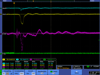
|
| 10.7 Amps (5.8481 MeV) | 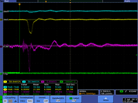
|
Energy Scan at Low Energy 6.5610 MeV
2nd Tune
Energy switch is in, linac operates at low energy
| Energy Switch | In (Low En Range) |
| Dipole Coil Current | |
| nominal e- Beam Energy () | MeV (mapping ) |
| Solenoid 1 | 10.1 A |
| Solenoid 2 | 9.6 A |
| Gun Hor | 0 A |
| Gun Ver | 0 A |
| Output Hor | + 0.2 A |
| Output Ver | + 0.1 A |
| Rep Rate | 3 |
| Gun HV | 10(Knob Setting) |
| Gun Grid Voltage | 9.5 (Knob Setting) |
| RF frequency | 2856.617 MHz |
| Modulator HV Power Supply | 3.97 (Knob Setting) |
| RF macro Pulse Length (FWHM) | 200 ns |
| Q1 (A) | +2.4 |
| Q2 (A) | +1 |
| Q3 (A) | -0.6 |
| Q4 (A) | -2.2 |
| Q5 (A) | + 2.8 |
| Q6 (A) | -1.2 |
| Q7 (A) | -4 |
| Q8 (A) | -4.9 |
| Q9 (A) | +5.5 |
| Q10 (A) | -4.8 |
| D1 & D2 (A) | 12 |
| Q7 (Amps | Current on 90 deg Faraday cup |
| 0 | 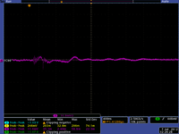
|
| 1 | 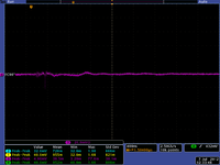
|
| 2 | 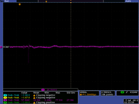
|
| 3 | 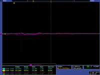
|
| 5 | 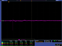
|
1. Tuning
Energy switch is in, linac operates at low energy
| Energy Switch | In (Low En Range) |
| Dipole Coil Current | |
| nominal e- Beam Energy () | 4 MeV (mapping ) |
| Solenoid 1 | 3.5 A |
| Solenoid 2 | 10.6 A |
| Gun Hor | 0.1 A |
| Gun Ver | -0.3 A |
| Output Hor | 0.1 A |
| Output Ver | 0.1 A |
| Rep Rate | 25 |
| Gun HV | 8.97(Knob Setting) |
| Gun Grid Voltage | 9.96 (Knob Setting) |
| RF frequency | 2856.730 MHz |
| Modulator HV Power Supply | 3.96 (Knob Setting) |
| RF macro Pulse Length (FWHM) | 200 ns |
| Q1 (A) | 0 |
| Q2 (A) | 0 |
| Q3 (A) | 0 |
| Q4 (A) | 0 |
| Q5 (A) | 0 |
| Q6 (A) | 0 |
| Scope on FC 1 | 34.2 mA 200 px |
| Scope on FC 2 | 200 px |
| Beam Spot | 200 px |
Deliver beam to the 90 FC
We were not able to deliver the beam to then end of the 90 deg beamline. We checked the hock-up of the 2nd dipole magnet, it was hocked up in a wrong way.
After we reconnected the dipole in the right way, we observed the beam at 90 deg Faraday cup.
At 8 MeV setting. I had 74 mA at FC1. After bending 45 I got 6 mA with Energy slits full open (3.44 cm). 6/74 = 8.1%.
Camera Triggering
Used Stanford pulser. External triggered by gun sync. Out put at "AB", "VAR". Cam trig sent from to "A_-_B". This works well at 30 reprate.
A = T + 2 micro second.
B = T + 11 micro second.