Difference between revisions of "Kiwi Dipole Mappings"
| Line 619: | Line 619: | ||
Mapping of the dipole was divided into 3 parts according to the path of the ideal particle. This trajectory of particle with ideal energy should go through a fringe field (approximately straight line) and dipole field (rotation of near 45 degree with dipole bending radius of 319 mm), and another fringe field (approximately straight line). We called them A2 (entering fringe field), Rotation and A1 (Exiting fringe field). | Mapping of the dipole was divided into 3 parts according to the path of the ideal particle. This trajectory of particle with ideal energy should go through a fringe field (approximately straight line) and dipole field (rotation of near 45 degree with dipole bending radius of 319 mm), and another fringe field (approximately straight line). We called them A2 (entering fringe field), Rotation and A1 (Exiting fringe field). | ||
| − | ==A2== | + | ==A2== |
| − | + | ||
| − | + | I= - 6.5 A I= - 15.25 A I= - 24 A I= - 33 A | |
| − | + | Z(mm) B (G) B (G) B (G) B (G) | |
| − | + | 81.50 -55.2500 -128.3700 200.6800 -273.6085 | |
| − | + | 82.50 -52.6000 -122.1600 -191.0000 -260.3194 | |
| − | + | 83.50 -50.0700 -116.2700 -181.7600 -247.6903 | |
| − | + | 84.50 -47.6700 -110.6800 -173.0100 -235.7135 | |
| − | + | 85.50 -45.4000 -105.3700 -164.6920 | |
| − | + | 87.50 -41.1800 -95.5400 -149.2710 -203.2767 | |
| − | + | 89.50 -37.3800 -86.6600 -135.3760 -184.2830 | |
| − | + | 91.50 -33.9600 -78.6600 -122.8530 -167.1615 | |
| − | + | 93.50 -30.8600 -71.4600 -111.5640 -151.7285 | |
| − | + | 95.50 -28.0800 -64.9700 -101.3870 -137.8432 | |
| − | + | 98.00 -25.1200 -57.7600 -90.1060 -122.3860 | |
| − | + | 100.00 -22.8900 -52.6200 -82.0500 -111.3860 | |
| − | + | 103.00 -19.9800 -45.8400 -71.4230 -96.9286 | |
| − | + | 105.00 -18.2600 -41.8600 -65.1930 -88.3740 | |
| − | + | 110.00 -14.6600 -33.5200 -52.1380 -70.5650 | |
| − | + | 115.00 -11.8500 -27.1700 -41.9210 | |
| − | + | 120.00 -9.6500 -22.0600 -34.0260 -45.8887 | |
| − | + | 130.00 -6.5400 -14.8400 -22.9290 -30.7577 | |
| − | + | 140.00 -4.5600 -10.2500 -15.7670 -21.0309 | |
| + | 150.00 -3.2600 -7.2600 -11.0980 -14.7070 | ||
| − | ==A1== | + | ==A1== |
| − | + | ||
| − | + | I= - 6.505 A I= - 15.25 A I= - 24 A I= - 33 A | |
| − | + | Z(mm) B (G) B (G) Z(mm) B (G) B (G) | |
| − | + | 137.50 -69.4460 -160.7070 137.50 -252.3900 -342.9800 | |
| − | + | 136.50 -66.4320 -153.7000 136.50 -241.2700 -328.0530 | |
| − | + | 135.50 -63.5170 -146.9330 135.50 -230.6500 -313.6100 | |
| − | + | 134.50 -60.7320 -140.4650 134.50 -220.5150 -299.7060 | |
| − | + | 133.50 -58.0720 -134.2840 133.50 -210.8160 -286.0330 | |
| − | + | 132.50 -128.3450 133.00 -206.0800 -279.6640 | |
| − | + | 132.00 -54.3030 -125.5330 132.00 -197.0500 -267.3660 | |
| − | + | 131.00 -51.9270 -120.0150 131.00 -188.4130 -255.5850 | |
| − | + | 130.00 -49.6620 -114.7500 130.00 -180.1390 -244.2880 | |
| − | + | 128.00 -45.4210 -104.9110 128.00 -164.6400 -223.1900 | |
| − | + | 126.00 -41.5550 -95.9450 126.00 -150.5300 -204.0060 | |
| − | + | 124.00 -38.0300 -87.7600 124.00 -137.6900 -186.4830 | |
| − | + | 122.00 -34.8100 -80.2900 122.00 -125.9700 -170.5440 | |
| − | + | 120.00 -31.8780 -73.4860 120.00 -115.2900 -156.0020 | |
| − | + | 118.00 -29.2060 -67.2900 118.00 -105.5500 -142.7470 | |
| − | + | 116.00 -26.7690 -61.6400 116.00 -96.6900 -130.6987 | |
| − | + | 114.00 -24.6392 -56.5000 114.00 -88.6240 -119.7218 | |
| − | + | 112.00 -22.6060 -51.5000 112.00 -81.2700 -109.7030 | |
| − | + | 110.00 -20.7550 -47.5500 110.00 -74.5700 -100.6170 | |
| − | + | 105.00 -7.6170 -38.4870 105.00 -60.3500 -81.2724 | |
| − | + | 100.00 -13.6900 -31.3000 100.00 -49.0700 -65.9450 | |
| − | + | 95.00 -11.2000 -25.6840 95.00 -40.1000 -53.7603 | |
| − | + | 90.00 -9.2140 -21.1000 90.00 -32.9500 -44.0770 | |
| − | + | 85.00 -7.6170 -17.4250 85.00 -27.3370 -36.3176 | |
| − | + | 80.00 -6.3283 -14.4650 80.00 -22.6950 -30.0751 | |
| − | + | 70.00 -4.4300 -10.1160 70.00 -15.8800 -20.9880 | |
| − | + | 60.00 -3.1525 -7.2000 60.00 -11.3140 -14.8445 | |
| − | + | 50.00 -2.2720 -5.2060 50.00 -8.1950 -10.6612 | |
| − | + | 40.00 -1.6530 -3.8125 40.00 -6.0240 -7.7550 | |
| − | + | 30.00 -1.2085 -2.8200 30.00 -4.4750 -5.6980 | |
| − | + | 20.00 -1.8830 -2.1020 20.00 -3.3570 -4.2240 | |
| − | + | 10.00 -0.6410 -1.5740 10.00 -2.3800 -3.1460 | |
| + | 0.00 -0.4590 -1.1800 0.00 -1.9360 -0.3540 | ||
Revision as of 23:33, 16 December 2011
File:Kiwi Dipole Magnet Mappings.pdf
1st Mapping
Tag Number: 079220
Bending magnet that was to be used with LCS (compact magnets) The horizontal and vertical tranlator have a range for 150 mm i.e. 15 cm.
Power on I = 20.4 A
| x (mm) | y (mm) | B (kG) | |
| 127 | 0 | ||
| 127 | 10 | -0.106 | |
| 127 | 20 | -0.169 | |
| 127 | 30 | -0.2729 | |
| 127 | 40 | -0.448 | |
| 127 | 50 | -0.728 | |
| 127 | 60 | -0.97 | |
| 127 | 70 | -1.025 | |
| 127 | 80 | -1.029 | |
| 127 | 90 | -1.03 | |
| 127 | 100 | -1.029 | |
| 127 | 110 | -1.028 | |
| 127 | 120 | -1.028 | |
| 127 | 130 | -1.028 | |
| 127 | 140 | -1.028 | |
| 127 | 150 | -1.028 | |
| y = 150 mm is roughly center of the bend. | |||
| 127 | 150 | -1.028 | |
| 127 | 140 | -1.031 | |
| 127 | 130 | -1.0342 | |
| 127 | 120 | -1.036 | |
| 127 | 110 | -1.036 | |
| 127 | 100 | -1.036 | |
| 127 | 90 | -1.036 | |
| 127 | 80 | -1.0355 | |
| 127 | 70 | -1.03 | |
| 127 | 60 | -0.977 | |
| 127 | 50 | -0.7354 | |
| 127 | 40 | -0.4527 | |
| 127 | 30 | -0.275 | |
| 127 | 20 | -0.17 | |
| 127 | 10 | -0.1066 | |
| 127 | 0 | -0.0673 | |
| Again | |||
| x (mm) | y (mm) | B (kG) | |
| 127 | 0 | ||
| 127 | 10 | -0.1062 | |
| 127 | 20 | -0.1699 | |
| 127 | 30 | -0.2738 | |
| 127 | 40 | -0.449 | |
| 127 | 50 | -0.7283 | edge of poles 100 px |
| 127 | 60 | -0.9712 | |
| 127 | 70 | -1.0253 | |
| 127 | 80 | -1.03 | |
| 127 | 90 | -1.03 | |
| 127 | 100 | -1.0298 | |
| 127 | 110 | -1.028 | |
| 127 | 120 | -1.0285 | |
| 127 | 130 | -1.0286 | |
| 127 | 140 | -1.0282 | |
| 127 | 150 | -1.0278 |
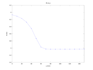
     y (mm)      B (kG)   error B (kG)
    0.00000    -0.06717     0.00015
   10.00000    -0.10627     0.00031
   20.00000    -0.16963     0.00055
   30.00000    -0.27390     0.00105
   40.00000    -0.44990     0.00248
   50.00000    -0.73057     0.00419
   60.00000    -0.97273     0.00374
   70.00000    -1.02677     0.00280
   80.00000    -1.03150     0.00350
   90.00000    -1.03200     0.00346
  100.00000    -1.03160     0.00383
  110.00000    -1.03067     0.00462
  120.00000    -1.03083     0.00448
  130.00000    -1.03027     0.00342
  140.00000    -1.02907     0.00168
  150.00000    -1.02793     0.00012
X at 127, Y at 150
| x (mm) | y (mm) | I | B (kG) | |
| 127 | 150 | 20.1 | -1.0279 | |
| 127 | 150 | 30.1 | -1.53 | |
| 127 | 150 | 25.1 | -1.2916 | |
| 127 | 150 | 20.1 | -1.0359 | |
| 127 | 150 | 15 | -0.781 | |
| 127 | 150 | 10 | -0.534 | |
| 127 | 150 | 5 | -0.277 | |
| 127 | 150 | 0 | -0.017 | |
| Again | ||||
| 127 | 150 | 0 | -0.01726 | |
| 127 | 150 | 5 | -0.266 | |
| 127 | 150 | 10 | -0.518 | |
| 127 | 150 | 15 | -0.7713 | |
| 127 | 150 | 20 | -1.02 | |
| 127 | 150 | 25 | -1.272 | |
| 127 | 150 | 30 | -1.52 |
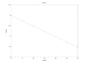
  I (Amps)    B (kG)    error B (kG)
   0.00000   -0.01713    0.00018
   5.00000   -0.27150    0.00778
  10.00000   -0.52600    0.01131
  15.00000   -0.77615    0.00686
  20.00000   -1.02795    0.01124
  25.00000   -1.28180    0.01386
  30.00000   -1.52500    0.00707
Vertical Scan
Power on I = 20 A
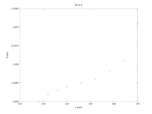
Gap width 5cm.
| x (mm) | y (mm) | B (kG) | |
| 135 (lower edge) | 150 | -1.0369 | |
| 132 | 150 | -1.0379 | |
| 129 | 150 | -1.0382 | |
| 126 | 150 | -1.0384 | |
| 123 | 150 | -1.0385 | |
| 120 | 150 | -1.0386 | |
| 118 | 150 | -1.0387 | |
| 116 | 150 | -1.0388 | |
| 114 | 150 | -1.039 |
   x (mm)      y(mm)       B(kG)
  135.0000   150.0000    -1.0369
  132.0000   150.0000    -1.0379
  129.0000   150.0000    -1.0382
  126.0000   150.0000    -1.0384
  123.0000   150.0000    -1.0385
  120.0000   150.0000    -1.0386
  118.0000   150.0000    -1.0387
  116.0000   150.0000    -1.0388
  114.0000   150.0000    -1.0390
Horizontal Scan
go for X = 124.5, y = 150 (dipole center), I = 20 A.
| x (mm) | y (mm) | I (A) | B (kG) | |
| 124.5 | 150 | 20 | -1.0388 | |
| 124.5 | 140 | 20 | -1.04 | |
| 124.5 | 130 | 20 | -1.04 | |
| 124.5 | 120 | 20 | -1.0409 | |
| 124.5 | 110 | 20 | -1.041 | |
| 124.5 | 100 | 20 | -1.0411 | |
| 124.5 | 90 | 20 | -1.041 | |
| 124.5 | 80 | 20 | -1.0408 | |
| 124.5 | 70 | 20 | -1.355 | This data is problematic. |
| 124.5 | 60 | 20 | -0.9799 | |
| 124.5 | 50 | 20 | -0.74 | |
| 124.5 | 40 | 20 | -0.457 | |
| 124.5 | 30 | 20 | -0.2776 | |
| 124.5 | 20 | 20 | -0.1718 | |
| 124.5 | 0 | 20 | -0.0684 |
Figure according to the data above. There is problem when y = 70 mm.
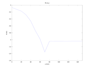
   x (mm)      y  (mm)       I (A)      B  (kG)
  124.50000   150.00000    20.00000    -1.03880
  124.50000   140.00000    20.00000    -1.04000
  124.50000   130.00000    20.00000    -1.04000
  124.50000   120.00000    20.00000    -1.04090
  124.50000   110.00000    20.00000    -1.04100
  124.50000   100.00000    20.00000    -1.04110
  124.50000    90.00000    20.00000    -1.04100
  124.50000    80.00000    20.00000    -1.04080
  124.50000    70.00000    20.00000    -1.03550
  124.50000    60.00000    20.00000    -0.97990
  124.50000    50.00000    20.00000    -0.74000
  124.50000    40.00000    20.00000    -0.45700
  124.50000    30.00000    20.00000    -0.27760
  124.50000    20.00000    20.00000    -0.17180
  124.50000     0.00000    20.00000    -0.06840
Figure according to the data above. The problem when y = 70 mm is changed to -1.0355
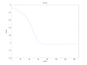
Power on X = 124.5, Y = 150
| x (mm) | y (mm) | I (A) | B (kG) | |
| 124.5 | 150 | 0 | -0.0123 | |
| 124.5 | 150 | 5 | -0.2676 | |
| 124.5 | 150 | 10 | -0.516 | |
| 124.5 | 150 | 15 | -0.771 | |
| 124.5 | 150 | 20 | -1.028 | |
| 124.5 | 150 | 25 | -1.2735 | |
| 124.5 | 150 | 30 | -1.5217 | |
| 124.5 | 150 | 30 | -1.5218 | |
| 124.5 | 150 | 25 | -1.287 | |
| 124.5 | 150 | 20 | -1.037 | |
| 124.5 | 150 | 15 | -0.7855 | |
| 124.5 | 150 | 10 | -0.5313 | |
| 124.5 | 150 | 5 | -0.2747 | |
| 124.5 | 150 | 0 | -0.0164 |
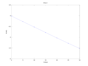
    I (A)      B(kG)    error B(kG)
  30.00000   -1.52175    0.00007
  25.00000   -1.28025    0.00955
  20.00000   -1.03250    0.00636
  15.00000   -0.77825    0.01025
  10.00000   -0.52365    0.01082
   5.00000   -0.27115    0.00502
   0.00000   -0.01435    0.00290
Tag Number: 42125
| x (mm) | y (mm) | I (A) | B (kG) | |
| 0 | 0 | Power off | ||
| 0 | 0 | 20 | ||
| 111.75 | 0 | 20 |
| x (mm) | y (mm) | I (A) | B (kG) |
| 111.75 | 10 | 20 | 0.0637 |
| 111.75 | 20 | 20 | 0.102 |
| 111.75 | 30 | 20 | 0.1675 |
| 111.75 | 40 | 20 | 0.2774 |
| 111.75 | 50 | 20 | 0.4654 |
| 111.75 | 60 | 20 | 0.756 |
| 111.75 | 70 | 20 | 0.9898 |
| 111.75 | 80 | 20 | 1.0312 |
| 111.75 | 90 | 20 | 1.0358 |
| 111.75 | 100 | 20 | 1.0362 |
| 111.75 | 110 | 20 | 1.0363 |
| 111.75 | 120 | 20 | 1.0363 |
| 111.75 | 130 | 20 | 1.0362 |
| 111.75 | 140 | 20 | 1.036 |
| 111.75 | 150 | 20 | 1.036 |
| 111.75 | 0 | 20 | 0.0402 |
| 111.75 | 10 | 20 | 0.0635 |
| 111.75 | 20 | 20 | 0.1022 |
| 111.75 | 30 | 20 | 0.1674 |
| 111.75 | 40 | 20 | 0.2773 |
| 111.75 | 50 | 20 | 0.4652 |
| 111.75 | 60 | 20 | 0.755 |
| 111.75 | 70 | 20 | 0.9828 |
| 111.75 | 80 | 20 | 1.0312 |
| 111.75 | 90 | 20 | 1.0358 |
| 111.75 | 100 | 20 | 1.0362 |
| 111.75 | 110 | 20 | 1.0362 |
| 111.75 | 120 | 20 | 1.03625 |
| 111.75 | 130 | 20 | 1.0362 |
| 111.75 | 140 | 20 | 1.036 |
| 111.75 | 150 | 20 | 1.036 |
| x (mm) | y (mm) | I (A) | B (kG) |
| 111.75 | 150 | 0 | 0.0076 |
| 111.75 | 150 | 5 | 0.263 |
| 111.75 | 150 | 10 | 0.52 |
| 111.75 | 150 | 15 | 0.7754 |
| 111.75 | 150 | 20 | 1.0313 |
| 111.75 | 150 | 25 | 1.2869 |
| 111.75 | 150 | 30 | 1.5389 |
| 111.75 | 150 | 30 | 1.5389 |
| 111.75 | 150 | 25 | 1.3 |
| 111.75 | 150 | 20 | 1.0484 |
| 111.75 | 150 | 15 | 0.7945 |
| 111.75 | 150 | 10 | 0.534 |
| 111.75 | 150 | 5 | 0.276 |
| 111.75 | 150 | 0 | 0.01386 |
| x (mm) | y (mm) | I (A) | B (kG) |
| 123.25 | 150 | 20 | 1.0339 |
| 120.25.25 | 150 | 20 | 1.0338 |
| 117.25 | 150 | 20 | 1.034 |
| 114.25 | 150 | 20 | 1.034 |
| 111.25 | 150 | 20 | 1.0342 |
| 111.25 | 150 | 20 | 1.0343 |
| 108.25 | 150 | 20 | 1.0342 |
| 105.25 | 150 | 20 | 1.0343 |
| 102.25 | 150 | 20 | 1.0344 |
| 99.25 | 150 | 20 | 1.03435 |
| x (mm) | y (mm) | I (A) | B (kG) |
| 111.25 | 150 | 20 | 1.0339 |
| 111.25 | 0 | 20 | 0.04 |
| 111.25 | 10 | 20 | 0.0633 |
| 111.25 | 20 | 20 | 0.102 |
| 111.25 | 30 | 20 | 0.1671 |
| 111.25 | 40 | 20 | 0.2767 |
| 111.25 | 50 | 20 | 0.4643 |
| 111.25 | 60 | 20 | 0.7544 |
| 111.25 | 70 | 20 | 0.9818 |
| 111.25 | 80 | 20 | 1.0295 |
| 111.25 | 90 | 20 | 1.034 |
| 111.25 | 100 | 20 | 1.0344 |
| 111.25 | 110 | 20 | 1.0345 |
| 111.25 | 120 | 20 | 1.0345 |
| 111.25 | 130 | 20 | 1.0345 |
| 111.25 | 140 | 20 | 4.0343 |
| 111.25 | 150 | 20 | 10.342 |
| 111.25 | 0 | 20 | 0.04 |
| 111.25 | 10 | 20 | 0.0632 |
| 111.25 | 20 | 20 | 0.1018 |
| 111.25 | 30 | 20 | 0.1669 |
| 111.25 | 40 | 20 | 0.2767 |
| 111.25 | 50 | 20 | 0.4639 |
| 111.25 | 60 | 20 | 0.754 |
| 111.25 | 70 | 20 | 0.9816 |
| 111.25 | 80 | 20 | 1.0294 |
| 111.25 | 90 | 20 | 1.034 |
| 111.25 | 100 | 20 | 1.0344 |
| 111.25 | 110 | 20 | 1.0344 |
| 111.25 | 120 | 20 | 1.0344 |
| 111.25 | 130 | 20 | 1.0343 |
| 111.25 | 140 | 20 | 4.0342 |
| 111.25 | 150 | 20 | 10.342 |
| x (mm) | y (mm) | I (A) | B (kG) |
| 111.25 | 43 mm | 0 | |
| 111.25 | 43 mm | 5 | 0.0822 |
| 111.25 | 43 mm | 10 | 0.1615 |
| 111.25 | 43 mm | 15 | 0.242 |
| 111.25 | 43 mm | 20 | 0.3227 |
| 111.25 | 43 mm | 25 | 0.4014 |
| 111.25 | 43 mm | 30 | 0.4793 |
| 111.25 | 43 mm | 0 | |
| 111.25 | 43 mm | 5 | 0.08 |
| 111.25 | 43 mm | 10 | 0.1613 |
| 111.25 | 43 mm | 15 | 0.242 |
| 111.25 | 43 mm | 20 | 0.3215 |
| 111.25 | 43 mm | 25 | 0.4 |
| 111.25 | 43 mm | 30 | 0.4783 |
2nd Mapping
Bending radius of dipole is 319 mm. The bending radius in measurement is r = 280 mm.
Mapping of the dipole was divided into 3 parts according to the path of the ideal particle. This trajectory of particle with ideal energy should go through a fringe field (approximately straight line) and dipole field (rotation of near 45 degree with dipole bending radius of 319 mm), and another fringe field (approximately straight line). We called them A2 (entering fringe field), Rotation and A1 (Exiting fringe field).
A2
       I= - 6.5 A	I= - 15.25 A	I= - 24 A	I= - 33 A
Z(mm) 	B (G)	        B (G)	         B (G)	         B (G)
81.50	-55.2500	-128.3700	200.6800	-273.6085
82.50	-52.6000	-122.1600	-191.0000	-260.3194
83.50	-50.0700	-116.2700	-181.7600	-247.6903
84.50	-47.6700	-110.6800	-173.0100	-235.7135
85.50	-45.4000	-105.3700	-164.6920
87.50	-41.1800	-95.5400	-149.2710	-203.2767
89.50	-37.3800	-86.6600	-135.3760	-184.2830
91.50	-33.9600	-78.6600	-122.8530	-167.1615
93.50	-30.8600	-71.4600	-111.5640	-151.7285
95.50	-28.0800	-64.9700	-101.3870	-137.8432
98.00	-25.1200	-57.7600	-90.1060	-122.3860
100.00	-22.8900	-52.6200	-82.0500	-111.3860
103.00	-19.9800	-45.8400	-71.4230	-96.9286
105.00	-18.2600	-41.8600	-65.1930	-88.3740
110.00	-14.6600	-33.5200	-52.1380	-70.5650
115.00	-11.8500	-27.1700	-41.9210
120.00	-9.6500 	-22.0600	-34.0260	-45.8887
130.00	-6.5400 	-14.8400	-22.9290	-30.7577
140.00	-4.5600	        -10.2500	-15.7670	-21.0309
150.00	-3.2600	        -7.2600	        -11.0980	-14.7070
A1
       I= - 6.505 A	I= - 15.25 A		I= - 24 A	        I= - 33 A
Z(mm) 	B (G)	         B (G)		        Z(mm) 	B (G)	        B (G)
137.50	-69.4460	-160.7070		137.50	-252.3900	-342.9800
136.50	-66.4320	-153.7000		136.50	-241.2700	-328.0530
135.50	-63.5170	-146.9330		135.50	-230.6500	-313.6100
134.50	-60.7320	-140.4650		134.50	-220.5150	-299.7060
133.50	-58.0720	-134.2840		133.50	-210.8160	-286.0330
132.50		        -128.3450		133.00	-206.0800	-279.6640
132.00	-54.3030	-125.5330		132.00	-197.0500	-267.3660
131.00	-51.9270	-120.0150		131.00	-188.4130	-255.5850
130.00	-49.6620	-114.7500		130.00	-180.1390	-244.2880
128.00	-45.4210	-104.9110		128.00	-164.6400	-223.1900
126.00	-41.5550	-95.9450		126.00	-150.5300	-204.0060
124.00	-38.0300	-87.7600		124.00	-137.6900	-186.4830
122.00	-34.8100	-80.2900		122.00	-125.9700	-170.5440
120.00	-31.8780	-73.4860		120.00	-115.2900	-156.0020
118.00	-29.2060	-67.2900		118.00	-105.5500	-142.7470
116.00	-26.7690	-61.6400		116.00	-96.6900	-130.6987
114.00	-24.6392	-56.5000		114.00	-88.6240	-119.7218
112.00	-22.6060	-51.5000		112.00	-81.2700	-109.7030
110.00	-20.7550	-47.5500		110.00	-74.5700	-100.6170
105.00	-7.6170	        -38.4870		105.00	-60.3500	-81.2724
100.00	-13.6900	-31.3000		100.00	-49.0700	-65.9450
95.00	-11.2000	-25.6840		95.00	-40.1000	-53.7603
90.00	-9.2140	        -21.1000		90.00	-32.9500	-44.0770
85.00	-7.6170	        -17.4250		85.00	-27.3370	-36.3176
80.00	-6.3283	        -14.4650		80.00	-22.6950	-30.0751
70.00	-4.4300	        -10.1160		70.00	-15.8800	-20.9880
60.00	-3.1525   	-7.2000 		60.00	-11.3140	-14.8445
50.00	-2.2720 	-5.2060 		50.00	-8.1950 	-10.6612
40.00	-1.6530 	-3.8125 		40.00	-6.0240 	-7.7550
30.00	-1.2085 	-2.8200 		30.00	-4.4750 	-5.6980
20.00	-1.8830 	-2.1020 	 	20.00	-3.3570 	-4.2240
10.00	-0.6410 	-1.5740 		10.00	-2.3800 	-3.1460
0.00	-0.4590 	-1.1800 		0.00	-1.9360 	-0.3540
