Difference between revisions of "Lab 13 RS"
| Line 105: | Line 105: | ||
I used: | I used: | ||
| − | <math>R_1 = (199.5 \pm 0.5)\ k\Omega </math> | + | <math>R_B = R_1 = (199.5 \pm 0.5)\ k\Omega </math> |
and | and | ||
<math>R_E = (100.0 \pm 0.5)\ \Omega </math> | <math>R_E = (100.0 \pm 0.5)\ \Omega </math> | ||
| Line 131: | Line 131: | ||
I used: | I used: | ||
| − | <math>R_3 = (100.0 \pm 0.5)\ k\Omega </math> | + | <math>R_B = R_3 = (100.0 \pm 0.5)\ k\Omega </math> |
and | and | ||
<math>R_E = (100.0 \pm 0.5)\ \Omega </math> | <math>R_E = (100.0 \pm 0.5)\ \Omega </math> | ||
Revision as of 20:45, 11 March 2011
DC Bipolar Transistor Curves
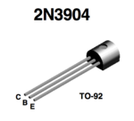
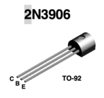
Data sheet for transistors.
Media:2N3904.pdfMedia:2N3906.pdf
Using 2N3904 is more srtaight forward in this lab.
Transistor circuit
1.) Identify the type (n-p-n or p-n-p) of transistor you are using and fill in the following specifications.
I am going to use n-p-n transistor 2N3904. Below are some specifications from data shits for this type of transistor:
| Value | Description | ||
|---|---|---|---|
| Collector-Base breakdown voltage | |||
| Emitter-Base Breakdown Voltage | |||
| Maximum Collector-Emitter Voltage | |||
| Maximum Collector-Emitter Voltage | |||
| Maximum Collector Current - Continuous | |||
| Transistor Power rating() | |||
| , | |||
| 40 | 300 | , | |
| 70 | 300 | , | |
| 100 | 300 | , | |
| 60 | 300 | , | |
| 30 | 300 | , | |
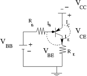
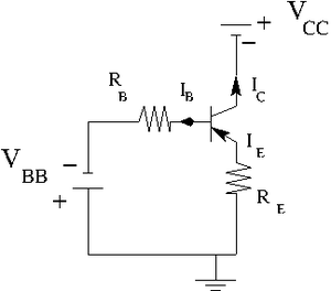
2.) Construct the circuit below according to the type of transistor you have.
Let .
variable power supply
.
Find the resistors you need to have
, , and
By measurements I was able to find that . So I am going to use this value. Also let picks up . So my current .
Now to get I need to use To get I need to use To get I need to use
3.) Measure the emitter current for several values of by changing such that the base current A is constant.
I used:
and
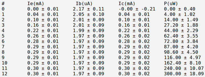
Below is the table with my measurements:
And below is my currents and power calculation:
Here:
4a.) Repeat the previous measurements for . Remember to keep so the transistor doesn't burn out
I used:
and
Below is the table with my measurements:
And below is my currents and power calculation:
Here:
4a.) Repeat the previous measurements for . Remember to keep so the transistor doesn't burn out
I used:
and
Below is the table with my measurements:
And below is my currents and power calculation:
Here:
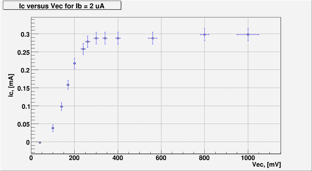
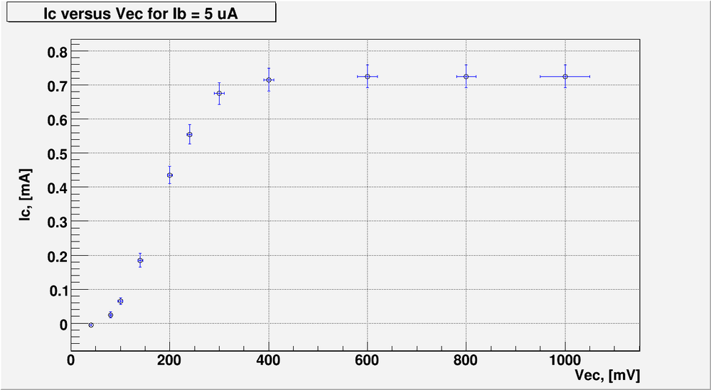
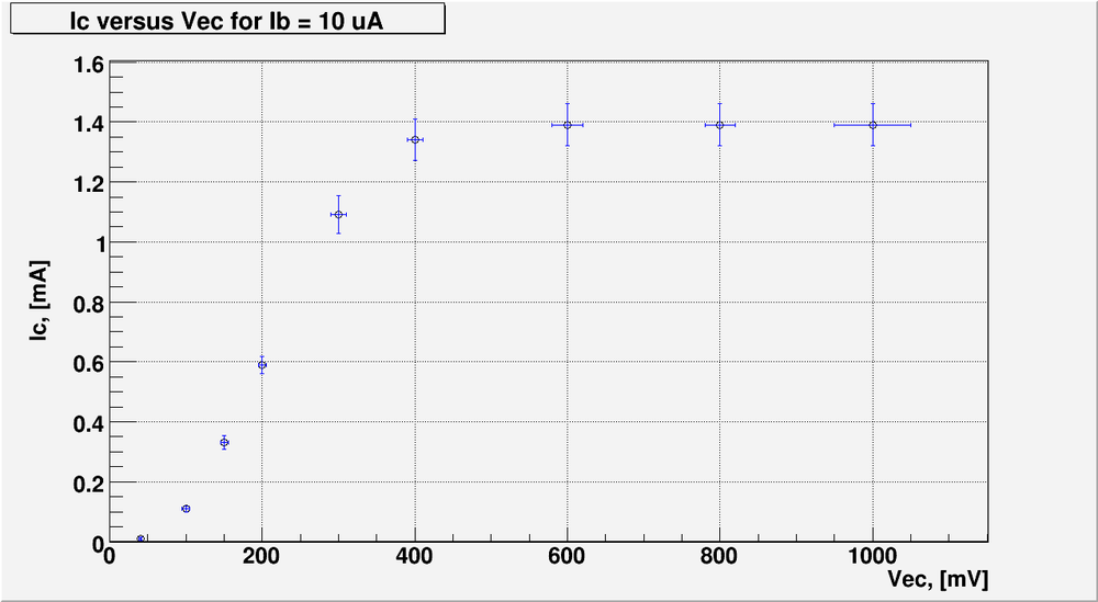
5.) Graph -vs- for each value of and above. (40 pnts)
Bellow is my plot for the case of
Bellow is my plot for the case of
Bellow is my plot for the case of
6.) Overlay points from the transistor's data sheet on the graph in part 5.).(10 pnts)
Questions
- Compare your measured value of or for the transistor to the spec sheet? (10 pnts)
- What is for the transistor?(10 pnts)
- The base must always be more _________(________) than the emitter for a npn (pnp)transistor to conduct I_C.(10 pnts)
- For a transistor to conduct I_C the base-emitter junction must be ___________ biased.(10 pnts)
- For a transistor to conduct I_C the collector-base junction must be ___________ biased.(10 pnts)
Extra credit
Measure the Base-Emmiter breakdown voltage. (10 pnts)
I expect to see a graph and a linear fit which is similar to the forward biased diode curves. Compare your result to what is reported in the data sheet.
Go Back to All Lab Reports Forest_Electronic_Instrumentation_and_Measurement
