Difference between revisions of "HRRL OTR Test Mar 3rd 2011"
| (68 intermediate revisions by 2 users not shown) | |||
| Line 56: | Line 56: | ||
| + | = Run = | ||
| + | == Field Emission Check == | ||
| + | |||
| + | |||
| + | Peak Current (mA): 160 | ||
| + | |||
| + | Rep Rate (Hz): 6 | ||
| + | |||
| + | Pulse width (ns): 200 | ||
| + | |||
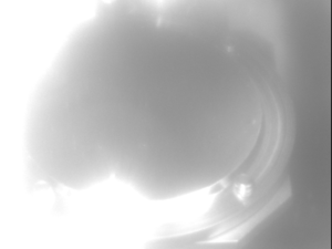
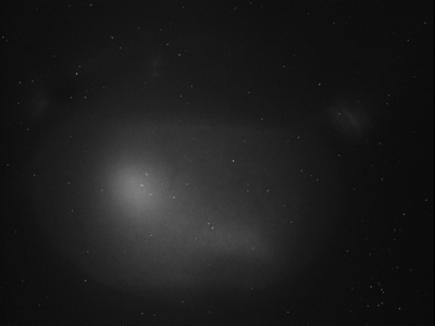
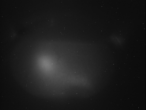
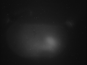
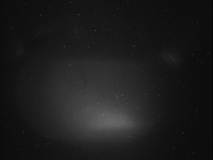
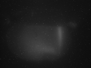
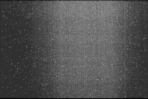
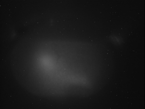
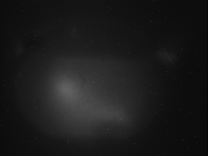
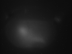
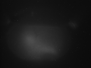
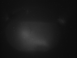
| + | === HV on, Filament on, RF on === | ||
| + | |||
| + | [[File:HRRL_Test_Mar_3rd_2001_FIled_Emission_Cehck_HV_on_Filament_on_RF_on.jpg | 400 px]] | ||
| + | |||
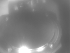
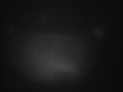
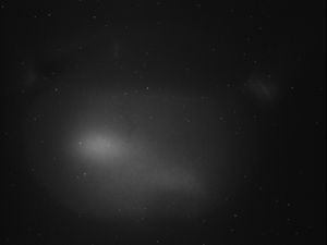
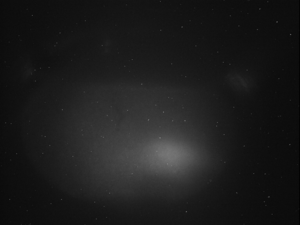
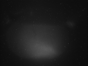
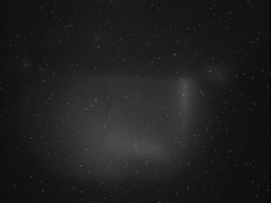
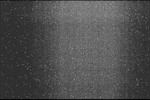
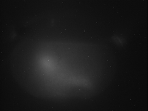
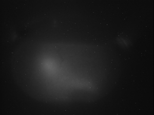
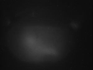
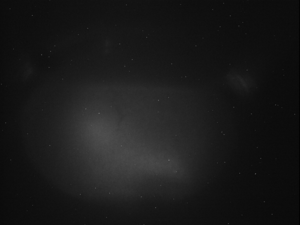
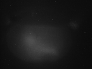
| + | === HV off, Filament on, RF on === | ||
| + | |||
| + | [[File:HRRL_Test_Mar_3rd_2001_FIled_Emission_Cehck_HV_off_Filament_on_RF_on.jpg | 400 px]] | ||
| + | |||
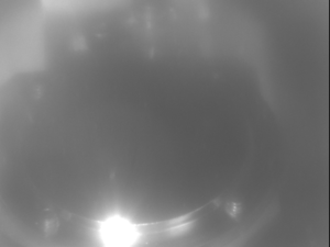
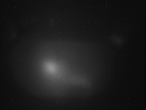
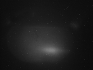
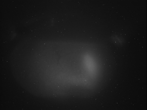
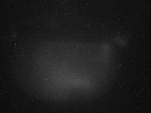
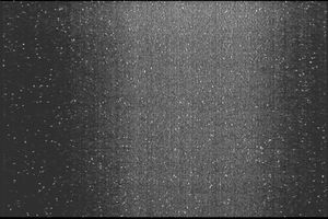
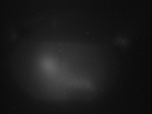
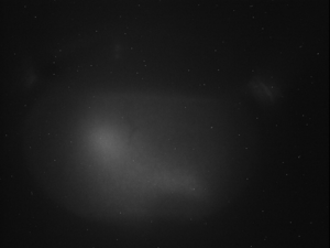
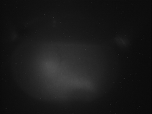
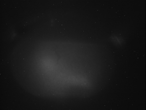
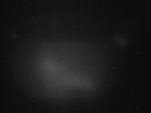
| + | === HV off, Filament on, RF off === | ||
| + | |||
| + | [[File:HRRL_Test_Mar_3rd_2001_FIled_Emission_Cehck_HV_off_Filament_on_RF_off.jpg | 400 px]] | ||
| + | |||
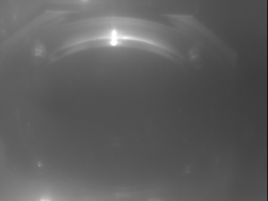
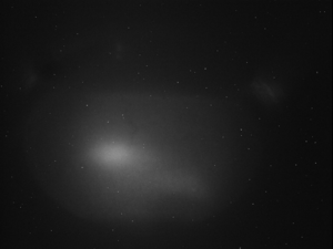
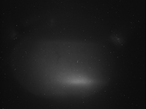
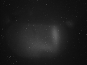
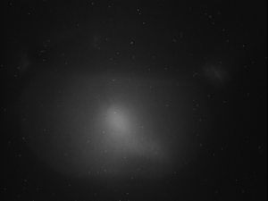
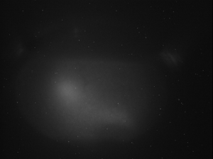
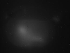
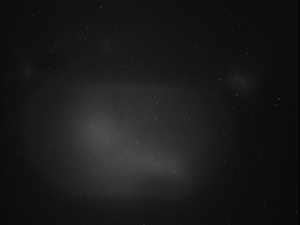
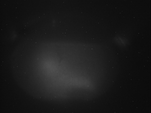
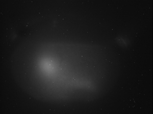
| + | === HV on, Filament on, RF off === | ||
| + | |||
| + | [[File:HRRL_Test_Mar_3rd_2001_FIled_Emission_Cehck_HV_on_Filament_on_RF_off.jpg | 400 px]] | ||
| + | |||
| + | |||
| + | |||
| + | |||
| + | |||
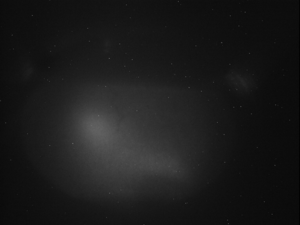
| + | === HV on, Filament on, RF on, Valve closed === | ||
| + | |||
| + | [[File:HRRL_Test_Mar_3rd_2001_FIled_Emission_Cehck_HV_on_Filament_on_RF_on_valve_closed.jpg | 400 px]] | ||
| + | |||
| + | === HV off, Filament on, RF on, Valve closed === | ||
| + | |||
| + | [[File:HRRL_Test_Mar_3rd_2001_FIled_Emission_Cehck_HV_off_Filament_on_RF_on_valve_closed.jpg | 400 px]] | ||
| + | |||
| + | === HV on, Filament on, RF off, Valve closed === | ||
| + | |||
| + | [[File:HRRL_Test_Mar_3rd_2001_FIled_Emission_Cehck_HV_on_Filament_on_RF_off_valve_closed.jpg | 400 px]] | ||
| + | |||
| + | === HV off, Filament on, RF off, Valve closed === | ||
| + | |||
| + | [[File:HRRL_Test_Mar_3rd_2001_FIled_Emission_Cehck_HV_off_Filament_on_RF_off_valve_closed.jpg | 400 px]] | ||
| + | |||
| + | === Conclusion === | ||
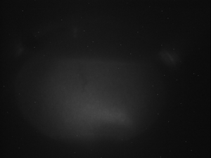
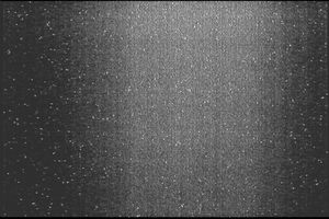
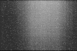
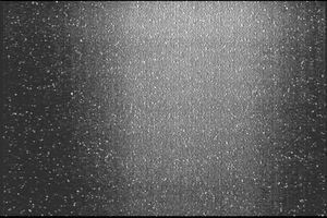
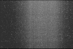
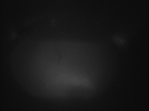
| + | When the HV is off, there were not any electrons from filament. We still see back ground light. This light was gone when the RF was turned off or vacuum valve (between screen and gun) was closed. So, this back ground light was due the the dark current that emitted from the cavity (field emission). | ||
| + | |||
| + | == Estimation of How Much off == | ||
| + | |||
| + | Rep Rate (Hz): 6 | ||
| + | |||
| + | Pulse width (ns): 200 | ||
| + | |||
| + | Take at least 3 images for each setting below. | ||
| + | |||
| + | The goal is to estimate how far things may be misaligned. Several assumption will be made. | ||
| + | |||
| + | ===Tuned for Max transmision to FC Just by steering Magnets === | ||
| + | |||
| + | |||
| + | Peak Current (mA): 160 | ||
| + | |||
| + | |||
| + | [[File:HRRL_OTR_Test_Mar_3rd_2011Tuned_for_Max_transmision_to_FC_Just_by_steering_Magnets.jpg | 300 px]] | ||
| + | |||
| + | ====Tuned for Max transmision to FC by using quads and steering Magnets==== | ||
| + | |||
| + | ==== Using 1st Triplets ==== | ||
| + | |||
| + | Peak Current (mA): 160 | ||
| + | |||
| + | [[File:HRRL_OTR_Test_Mar_3rd_2011Tuned_for_Max_transmision_to_FC_by_steering_Magnets_and_quads_1st_triplet.jpg | 300 px]] | ||
| + | |||
| + | |||
| + | ==== Using 2nd Triplets ==== | ||
| + | |||
| + | Peak Current (mA): 160 | ||
| + | |||
| + | [[File:HRRL_OTR_Test_Mar_3rd_2011Tuned_for_Max_transmision_to_FC_by_steering_Magnets_and_quads_2nd_triplet.jpg | 300 px]] | ||
| + | |||
| + | |||
| + | === Using Both Triplets === | ||
| + | |||
| + | Peak Current (mA): 160 | ||
| + | |||
| + | [[File:HRRL_OTR_Test_Mar_3rd_2011Tuned_for_Max_transmision_to_FC_by_steering_Magnets_and_quads_both_triplet.jpg | 300 px]] | ||
| + | |||
| + | ===Tuned for Min Quad deflection=== | ||
| + | |||
| + | Find the spot that when we change quad currents, center of the beam spot does not change or change the lest. | ||
| + | |||
| + | Rep Rate (Hz): 6 | ||
| + | |||
| + | Pulse width (ns): 200 | ||
| + | |||
| + | ==== Quqads off ==== | ||
| + | |||
| + | Peak Current (mA): 35 | ||
| + | |||
| + | Quads off: | ||
| + | |||
| + | [[File:HRRL_OTR_Test_Mar_3rd_2011_Tuned for_Min_Quad_deflection_spot_quads_off.jpg | 300 px]] | ||
| + | |||
| + | ==== 1st quad of the 1st triplet on ==== | ||
| + | |||
| + | 1st quad of the 1st triplet power supply at (A): 2 | ||
| + | |||
| + | [[File:HRRL_OTR_Test_Mar_3rd_2011_Tuned for_Min_Quad_deflection_spot_1st_quad_of_1st_Triplet_power_supply_at_2Amp.jpg | 300 px]] | ||
| + | |||
| + | 1st quad of the 1st triplet power supply at (A): 4 | ||
| + | |||
| + | [[File:HRRL_OTR_Test_Mar_3rd_2011_Tuned for_Min_Quad_deflection_spot_1st_quad_of_1st_Triplet_power_supply_at_4Amp.jpg | 300 px]] | ||
| + | |||
| + | 1st quad of the 1st triplet power supply at (A): 6 | ||
| + | |||
| + | [[File:HRRL_OTR_Test_Mar_3rd_2011_Tuned for_Min_Quad_deflection_spot_1st_quad_of_1st_Triplet_power_supply_at_6Amp.jpg | 300 px]] | ||
| + | |||
| + | 1st quad of the 1st triplet power supply at (A): 8 | ||
| + | |||
| + | [[File:HRRL_OTR_Test_Mar_3rd_2011_Tuned for_Min_Quad_deflection_spot_1st_quad_of_1st_Triplet_power_supply_at_8Amp.jpg | 300 px]] | ||
| + | |||
| + | 1st quad of the 1st triplet power supply at (A): 10 | ||
| + | |||
| + | [[File:HRRL_OTR_Test_Mar_3rd_2011_Tuned for_Min_Quad_deflection_spot_1st_quad_of_1st_Triplet_power_supply_at_10Amp.jpg | 300 px]] | ||
| + | |||
| + | |||
| + | |||
| + | |||
| + | |||
| + | ==== 2nd quad of the 1st triplet on ==== | ||
| + | |||
| + | 2nd quad of the 1st triplet power supply at (A): 2 | ||
| + | |||
| + | [[File:HRRL_OTR_Test_Mar_3rd_2011_Tuned for_Min_Quad_deflection_spot_2nd_quad_of_1st_Triplet_power_supply_at_2Amp.jpg | 300 px]] | ||
| + | |||
| + | 2nd quad of the 1st triplet power supply at (A): 4 | ||
| + | |||
| + | [[File:HRRL_OTR_Test_Mar_3rd_2011_Tuned for_Min_Quad_deflection_spot_2nd_quad_of_1st_Triplet_power_supply_at_4Amp.jpg | 300 px]] | ||
| + | |||
| + | 2nd quad of the 1st triplet power supply at (A): 6 | ||
| + | |||
| + | [[File:HRRL_OTR_Test_Mar_3rd_2011_Tuned for_Min_Quad_deflection_spot_2nd_quad_of_1st_Triplet_power_supply_at_6Amp.jpg | 300 px]] | ||
| + | |||
| + | 2nd quad of the 1st triplet power supply at (A): 8 | ||
| + | |||
| + | [[File:HRRL_OTR_Test_Mar_3rd_2011_Tuned for_Min_Quad_deflection_spot_2nd_quad_of_1st_Triplet_power_supply_at_8Amp.jpg | 300 px]] | ||
| + | |||
| + | 2nd quad of the 1st triplet power supply at (A): 10 | ||
| + | |||
| + | [[File:HRRL_OTR_Test_Mar_3rd_2011_Tuned for_Min_Quad_deflection_spot_2nd_quad_of_1st_Triplet_power_supply_at_10Amp.jpg | 300 px]] | ||
| + | |||
| + | ===Tune on center of Target=== | ||
| + | |||
| + | |||
| + | Rep Rate (Hz): 6 | ||
| + | Pulse width (ns): 200 | ||
| + | Peak Current (mA): 120 | ||
| + | |||
| + | Tuned on center of the target: | ||
| + | |||
| + | [[File:HRRL_OTR_Test_Mar_3rd_2011_Tuned on_center_of_Target_Beam_On.jpg | 300 px]] | ||
| + | |||
| + | |||
| + | Rf on, HV off (for back ground subtraction): | ||
| + | |||
| + | [[File:HRRL_OTR_Test_Mar_3rd_2011_Tuned on_center_of_Target_HV_Off_RF_On_for_bg_subtraction.jpg | 300 px]] | ||
| + | |||
| + | |||
| + | No beam, light is on: | ||
| + | |||
| + | [[File:HRRL_OTR_Test_Mar_3rd_2011_Tuned on_center_of_Target_No_Beam.jpg | 300 px]] | ||
| + | |||
| + | |||
| + | === Conclusion === | ||
| + | |||
| + | The center of the target, the beam spot has maximum transmision to FC, and min quad deflection beam spot are at different positions. Thus, beam line is not aliened. | ||
| + | |||
| + | == OTR Check Polarization== | ||
| + | |||
| + | Analog camera focused at infinity, and place such that lens is touching the window. | ||
| + | |||
| + | Pulse width (FMHM): 200 ns | ||
| + | |||
| + | Peak Current: 160 mA | ||
| + | |||
| + | Camera focused at infinity. | ||
| + | |||
| + | === No polarizer === | ||
| + | |||
| + | Accelerator off, back ground | ||
| + | |||
| + | [[File:HRRL_OTR_Test_Mar_3rd_2011_OTR_Check_Polarization_No_polarizer_Back_Ground.jpg | 300 px ]] | ||
| + | |||
| + | ==== 50 Hz Rep Rate ==== | ||
| + | |||
| + | [[File:HRRL_OTR_Test_Mar_3rd_2011_OTR_Check_Polarization_No_polarizer_50Hz_1.jpg | 300 px ]] | ||
| + | [[File:HRRL_OTR_Test_Mar_3rd_2011_OTR_Check_Polarization_No_polarizer_50Hz_2.jpg | 300 px ]] | ||
| + | |||
| + | ==== 291 Hz Rep Rate ==== | ||
| + | |||
| + | [[File:HRRL_OTR_Test_Mar_3rd_2011_OTR_Check_Polarization_No_polarizer_291Hz_1.jpg | 300 px ]] | ||
| + | [[File:HRRL_OTR_Test_Mar_3rd_2011_OTR_Check_Polarization_No_polarizer_291Hz_2.jpg | 300 px ]] | ||
| + | |||
| + | === Polarization of the Polarizer Parallel to the Beam Line Direction === | ||
| + | |||
| + | |||
| + | [[File:HRRL_OTR_Test_Mar_3rd_2011_OTR_Check_Polarization_polarizer_Parellel_to_BeamLine_80Hz_1.jpg | 300 px ]] | ||
| + | [[File:HRRL_OTR_Test_Mar_3rd_2011_OTR_Check_Polarization_polarizer_Parellel_to_BeamLine_80Hz_2.jpg | 300 px ]] | ||
| + | |||
| + | |||
| + | === Polarization of the Polarizer Perpendicular to the Beam Line Direction === | ||
| + | |||
| + | [[File:HRRL_OTR_Test_Mar_3rd_2011_OTR_Check_Polarization_perpendicular_Parellel_to_BeamLine_80Hz_1.jpg | 300 px ]] | ||
| + | [[File:HRRL_OTR_Test_Mar_3rd_2011_OTR_Check_Polarization_perpendicular_Parellel_to_BeamLine_80Hz_2.jpg | 300 px ]] | ||
| + | |||
| + | == Time Slice Study of the OTR == | ||
| + | |||
| + | Take pictures at different time slices from the trigger. | ||
| + | |||
| + | This means take a picture and then delay the trigger pulse to the camera relative to the RF. Perhaps the light has a time structure. | ||
| + | |||
| + | Rep Rate (Hz): 6 | ||
| + | |||
| + | Pulse width (ns): 200 | ||
| + | |||
| + | === 160 mA peak Current === | ||
| + | |||
| + | Peak Current (mA): 160 | ||
| + | |||
| + | |||
| + | [[File:HRRL_OTR_Test_Mar_3rd_2011_Time_Slice_Study_Delayed_160mA_0ns.jpg | 300 px]] | ||
| + | [[File:HRRL_OTR_Test_Mar_3rd_2011_Time_Slice_Study_Delayed_160mA_1ns.jpg | 300 px]] | ||
| + | [[File:HRRL_OTR_Test_Mar_3rd_2011_Time_Slice_Study_Delayed_160mA_2ns.jpg | 300 px]] | ||
| + | [[File:HRRL_OTR_Test_Mar_3rd_2011_Time_Slice_Study_Delayed_160mA_4ns.jpg | 300 px]] | ||
| + | [[File:HRRL_OTR_Test_Mar_3rd_2011_Time_Slice_Study_Delayed_160mA_8ns.jpg | 300 px]] | ||
| + | [[File:HRRL_OTR_Test_Mar_3rd_2011_Time_Slice_Study_Delayed_160mA_16ns.jpg | 300 px]] | ||
| + | [[File:HRRL_OTR_Test_Mar_3rd_2011_Time_Slice_Study_Delayed_160mA_32ns.jpg | 300 px]] | ||
| + | [[File:HRRL_OTR_Test_Mar_3rd_2011_Time_Slice_Study_Delayed_160mA_64ns.jpg | 300 px]] | ||
| + | [[File:HRRL_OTR_Test_Mar_3rd_2011_Time_Slice_Study_Delayed_160mA_96ns.jpg | 300 px]] | ||
| + | [[File:HRRL_OTR_Test_Mar_3rd_2011_Time_Slice_Study_Delayed_160mA_127ns.jpg | 300 px]] | ||
| + | |||
| + | |||
| + | |||
| + | |||
| + | === 105 mA peak Current === | ||
| + | |||
| + | Peak Current (mA): 105 | ||
| + | |||
| + | |||
| + | [[File:HRRL_OTR_Test_Mar_3rd_2011_Time_Slice_Study_Delayed_105mA_0ns.jpg | 300 px]] | ||
| + | [[File:HRRL_OTR_Test_Mar_3rd_2011_Time_Slice_Study_Delayed_105mA_1ns.jpg | 300 px]] | ||
| + | [[File:HRRL_OTR_Test_Mar_3rd_2011_Time_Slice_Study_Delayed_105mA_2ns.jpg | 300 px]] | ||
| + | [[File:HRRL_OTR_Test_Mar_3rd_2011_Time_Slice_Study_Delayed_105mA_4ns.jpg | 300 px]] | ||
| + | [[File:HRRL_OTR_Test_Mar_3rd_2011_Time_Slice_Study_Delayed_105mA_8ns.jpg | 300 px]] | ||
| + | [[File:HRRL_OTR_Test_Mar_3rd_2011_Time_Slice_Study_Delayed_105mA_16ns.jpg | 300 px]] | ||
| + | [[File:HRRL_OTR_Test_Mar_3rd_2011_Time_Slice_Study_Delayed_105mA_32ns.jpg | 300 px]] | ||
| + | [[File:HRRL_OTR_Test_Mar_3rd_2011_Time_Slice_Study_Delayed_105mA_64ns.jpg | 300 px]] | ||
| + | [[File:HRRL_OTR_Test_Mar_3rd_2011_Time_Slice_Study_Delaye_105mAd_96ns.jpg | 300 px]] | ||
| + | [[File:HRRL_OTR_Test_Mar_3rd_2011_Time_Slice_Study_Delayed_105mA_127ns.jpg | 300 px]] | ||
| + | |||
| + | == Far field== | ||
| + | |||
| + | Now return the camera trigger back to the original location in time. Focus at infinity and try to observe polarization. | ||
| + | |||
| + | |||
| + | = Report = | ||
| + | |||
| + | == Field Emission == | ||
| + | |||
| + | {| border="1" |cellpadding="20" cellspacing="0 | ||
| + | |- | ||
| + | | [[File:HRRL_Test_Mar_3rd_2001_FIled_Emission_Cehck_HV_on_Filament_on_RF_on.jpg | 300 px|thumb|HV on, RF on.]] | ||
| + | | [[File:HRRL_Test_Mar_3rd_2001_FIled_Emission_Cehck_HV_off_Filament_on_RF_on.jpg| 300 px|thumb|HV off, RF on.]] | ||
| + | |- | ||
| + | | [[File:HRRL_Test_Mar_3rd_2001_FIled_Emission_Cehck_HV_off_Filament_on_RF_off.jpg | 300 px|thumb|HV off, RF off.]] | ||
| + | | [[File:HRRL_Test_Mar_3rd_2001_FIled_Emission_Cehck_HV_on_Filament_on_RF_on_valve_closed.jpg | 300 px|thumb| HV on, RF on, Valve closed. ]] | ||
| + | |}<br> | ||
| + | |||
| + | When the HV is off, there were not any electrons from filament. We still see back ground light. This light was gone when the RF was turned off or vacuum valve (between screen and gun) was closed. So, this back ground light was due the the dark current that emitted from the cavity (field emission). | ||
| + | |||
| + | == Beam Alignment == | ||
| + | |||
| + | |||
| + | {| border="1" |cellpadding="20" cellspacing="0 | ||
| + | |- | ||
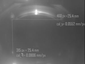
| + | | [[File:HRRL_OTR_Test_Mar_3rd_2011_Tuned on_center_of_Target_No_Beam.jpg | 300 px|thumb| No beam, light is on. ]] | ||
| + | | [[File:HRRL_OTR_Test_Mar_3rd_2011_Tuned on_center_of_Target_No_Beam_Calibration.jpg | 300 px|thumb| No beam, light is on for calibration. ]] | ||
| + | |- | ||
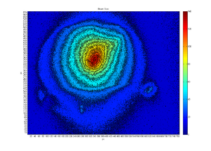
| + | | [[File:HRRL_OTR_Test_Mar_3rd_2011_Tuned on_center_of_Target_Beam_On.jpg | 300 px|thumb| Tuned on center of the target. ]] | ||
| + | | [[File:HRRL_OTR_Test_Mar_3rd_2011_Tuned on_center_of_Target_Beam_On_Contour.jpg | 300 px|thumb| Tuned on center of the target (contour). ]] | ||
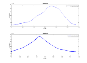
| + | | [[File:HRRL_OTR_Test_Mar_3rd_2011_Tuned on_center_of_Target_Beam_On_Histogram.jpg | 300 px|thumb| Tuned on center of the target projection (histograms). ]] | ||
| + | |- | ||
| + | |||
| + | | [[File:HRRL_OTR_Test_Mar_3rd_2011Tuned_for_Max_transmision_to_FC_Just_by_steering_Magnets.jpg | 300 px|thumb| Tuned for maximum transmision to FC just by steering magnets. ]] | ||
| + | | [[File:HRRL_OTR_Test_Mar_3rd_2011Tuned_for_Max_transmision_to_FC_Just_by_steering_Magnets_Contour.jpg | 300 px|thumb| Tuned for maximum transmision to FC just by steering magnets (contour). ]] | ||
| + | | [[File:HRRL_OTR_Test_Mar_3rd_2011Tuned_for_Max_transmision_to_FC_Just_by_steering_Magnets_Histogram.jpg | 300 px|thumb| Tuned for maximum transmision to FC just by steering magnets projection (histograms). ]] | ||
| + | |- | ||
| + | |||
| + | | [[File:HRRL_OTR_Test_Mar_3rd_2011_Tuned for_Min_Quad_deflection_spot_quads_off.jpg | 300 px|thumb| Tuned for min quad deflection (quads off). ]] | ||
| + | | [[File:HRRL_OTR_Test_Mar_3rd_2011_Tuned for_Min_Quad_deflection_spot_quads_off_Contour.jpg | 300 px|thumb| Tuned for min quad deflection (quads off) (contour). ]] | ||
| + | | [[File:HRRL_OTR_Test_Mar_3rd_2011_Tuned for_Min_Quad_deflection_spot_quads_off_Histogram.jpg | 300 px|thumb| Tuned for min quad deflection (quads off) projection (histograms). ]] | ||
| + | |||
| + | |}<br> | ||
| + | |||
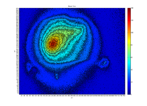
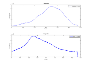
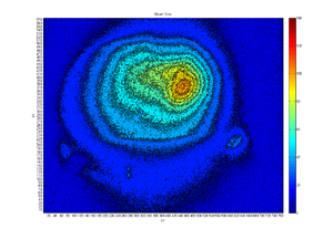
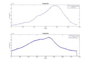
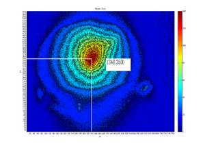
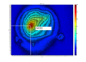
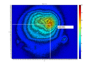
| + | The center of the target, the beam spot has maximum transmision to FC, and min quad deflection beam spot are at different positions. Thus, beam line is not aliened. | ||
| + | |||
| + | {| border="1" |cellpadding="20" cellspacing="0 | ||
| + | |- | ||
| + | | [[File:HRRL_OTR_Test_Mar_3rd_2011_Tuned on_center_of_Target_Beam_On.jpg | 300 px|thumb| ]] | ||
| + | | [[File:HRRL_OTR_Test_Mar_3rd_2011Tuned_for_Max_transmision_to_FC_Just_by_steering_Magnets.jpg | 300 px|thumb| ]] | ||
| + | | [[File:HRRL_OTR_Test_Mar_3rd_2011_Tuned for_Min_Quad_deflection_spot_quads_off.jpg | 300 px|thumb| ]] | ||
| + | |- | ||
| + | | [[File:HRRL_OTR_Test_Mar_3rd_2011_Tuned on_center_of_Target_Beam_On_Contour_Marked.jpg | 300 px|thumb| Tuned on center of the target (contour). Beam center at (340,350). ]] | ||
| + | |||
| + | | [[File:HRRL_OTR_Test_Mar_3rd_2011Tuned_for_Max_transmision_to_FC_Just_by_steering_Magnets_Contour_Marked.jpg | 300 px|thumb| Tuned for maximum transmision to FC just by steering magnets (contour). Beam center at (240,355). Off from center of the target by (100,5) pixels. Which is (5.52 mm,0.403 mm) ]] | ||
| + | |||
| + | | [[File:HRRL_OTR_Test_Mar_3rd_2011_Tuned for_Min_Quad_deflection_spot_quads_off_Contour_Marked.jpg | 300 px|thumb| Tuned for min quad deflection (quads off) (contour). Beam center at (450,365). Off from center of the target by (110,5) pixels. Which is (6.072 mm,1.209 mm). ]] | ||
| + | |}<br> | ||
| + | |||
| + | Distance between FC to OTR is 56 cm. They are off by 0.552 cm. They angle beam was going through them should be arctan(0.552/56)= 0.564754393 degree. | ||
| + | |||
| + | The distance from the exit of the Cavity to the OTR target is 353 cm. | ||
| + | |||
| + | <math>\frac{l}{353}=\frac{0.552}{56}</math> | ||
| + | |||
| + | <math>l=\frac{0.552}{56} \times 353= 3.479~cm</math> | ||
| + | |||
| + | == OTR Light Verification == | ||
| + | |||
| + | |||
| + | {| border="1" |cellpadding="20" cellspacing="0 | ||
| + | |- | ||
| + | | [[File:HV_off_RF_on_200ns_160mA_Polarizer_Parellel_to_Beamline_80Hz_1_projection.png | 300 px|thumb| Polarizer parallel the beam direction. ]] | ||
| + | | [[File:HV_off_RF_on_200ns_160mA_Polarizer_Parellel_to_Beamline_80Hz_2_projection.png | 300 px|thumb| Polarizer parallel the beam direction. ]] | ||
| + | |- | ||
| + | | [[File:HV_off_RF_on_200ns_160mA_Polarizer_Perpendicular_to_Beamline_80Hz_1_projection.png | 300 px|thumb| Polarizer perpendicular the beam direction. ]] | ||
| + | | [[File:HV_off_RF_on_200ns_160mA_Polarizer_Perpendicular_to_Beamline_80Hz_2_projection.png | 300 px|thumb| Polarizer perpendicular the beam direction. ]] | ||
| + | |||
| + | |}<br> | ||
| + | |||
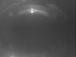
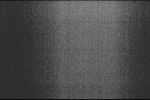
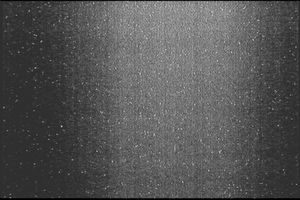
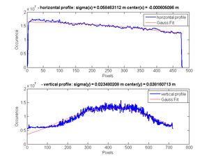
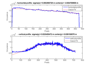
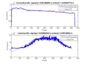
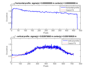
| + | A polarizer was placed perpendicular and parallel to the beam line direction to check it the light we were sing is polarized or not. Projections were do to look at the occurrence of incidents. From these results, it is convincing to say light is polarized. The noise is too high with analog camera that were used. Further investigation need to be done with better camera. | ||
Back to [[Positrons]] | Back to [[Positrons]] | ||
Latest revision as of 02:59, 10 March 2011
Preparation
JAI Camera Setup
Target in:
Target out:
Target in after shielded:
Objectives
Determined if the steering magnets of the gun are connected to power supply
1. Physically check looking at wires.
2. Change currents on the steering magnet, and observe position of the beam spot. If changes then, connected.
Tune beam using Linac optics only
Chad will tune up the beam using steering elements which are within the HRRL Linac only.
Determined if the OTR target is centered on the beam line
With all beam line magnets off, observe the beam spot at the OTR target. If the beam is centered on the OTR target, then OTR target MAY be centered on the beam line.
Polarization test
Insert a polarizer film. Take several picture for different orientations without changing beam properties.
Angel is measured with respect to:
| Polarizer Angel | Iamge |
| 200 px | 200 px |
Determined if the quads are centered on the beam line
The power supplies for ALL quads should be off.
Turn on Quad closesst to HRRL
If the beam deflects, try to align quad so there is no deflection
Turn on Quad closest to OTR target
If the beam deflects, try to align quad so there is no deflection
Run
Field Emission Check
Peak Current (mA): 160
Rep Rate (Hz): 6
Pulse width (ns): 200
HV on, Filament on, RF on
HV off, Filament on, RF on
HV off, Filament on, RF off
HV on, Filament on, RF off
HV on, Filament on, RF on, Valve closed
HV off, Filament on, RF on, Valve closed
HV on, Filament on, RF off, Valve closed
HV off, Filament on, RF off, Valve closed
Conclusion
When the HV is off, there were not any electrons from filament. We still see back ground light. This light was gone when the RF was turned off or vacuum valve (between screen and gun) was closed. So, this back ground light was due the the dark current that emitted from the cavity (field emission).
Estimation of How Much off
Rep Rate (Hz): 6
Pulse width (ns): 200
Take at least 3 images for each setting below.
The goal is to estimate how far things may be misaligned. Several assumption will be made.
Tuned for Max transmision to FC Just by steering Magnets
Peak Current (mA): 160
Tuned for Max transmision to FC by using quads and steering Magnets
Using 1st Triplets
Peak Current (mA): 160
Using 2nd Triplets
Peak Current (mA): 160
Using Both Triplets
Peak Current (mA): 160
Tuned for Min Quad deflection
Find the spot that when we change quad currents, center of the beam spot does not change or change the lest.
Rep Rate (Hz): 6
Pulse width (ns): 200
Quqads off
Peak Current (mA): 35
Quads off:
1st quad of the 1st triplet on
1st quad of the 1st triplet power supply at (A): 2
1st quad of the 1st triplet power supply at (A): 4
1st quad of the 1st triplet power supply at (A): 6
1st quad of the 1st triplet power supply at (A): 8
1st quad of the 1st triplet power supply at (A): 10
2nd quad of the 1st triplet on
2nd quad of the 1st triplet power supply at (A): 2
2nd quad of the 1st triplet power supply at (A): 4
2nd quad of the 1st triplet power supply at (A): 6
2nd quad of the 1st triplet power supply at (A): 8
2nd quad of the 1st triplet power supply at (A): 10
Tune on center of Target
Rep Rate (Hz): 6 Pulse width (ns): 200 Peak Current (mA): 120
Tuned on center of the target:
Rf on, HV off (for back ground subtraction):
No beam, light is on:
Conclusion
The center of the target, the beam spot has maximum transmision to FC, and min quad deflection beam spot are at different positions. Thus, beam line is not aliened.
OTR Check Polarization
Analog camera focused at infinity, and place such that lens is touching the window.
Pulse width (FMHM): 200 ns
Peak Current: 160 mA
Camera focused at infinity.
No polarizer
Accelerator off, back ground
50 Hz Rep Rate
291 Hz Rep Rate
Polarization of the Polarizer Parallel to the Beam Line Direction
Polarization of the Polarizer Perpendicular to the Beam Line Direction
Time Slice Study of the OTR
Take pictures at different time slices from the trigger.
This means take a picture and then delay the trigger pulse to the camera relative to the RF. Perhaps the light has a time structure.
Rep Rate (Hz): 6
Pulse width (ns): 200
160 mA peak Current
Peak Current (mA): 160
105 mA peak Current
Peak Current (mA): 105
Far field
Now return the camera trigger back to the original location in time. Focus at infinity and try to observe polarization.
Report
Field Emission
When the HV is off, there were not any electrons from filament. We still see back ground light. This light was gone when the RF was turned off or vacuum valve (between screen and gun) was closed. So, this back ground light was due the the dark current that emitted from the cavity (field emission).
Beam Alignment
The center of the target, the beam spot has maximum transmision to FC, and min quad deflection beam spot are at different positions. Thus, beam line is not aliened.
Distance between FC to OTR is 56 cm. They are off by 0.552 cm. They angle beam was going through them should be arctan(0.552/56)= 0.564754393 degree.
The distance from the exit of the Cavity to the OTR target is 353 cm.
OTR Light Verification
A polarizer was placed perpendicular and parallel to the beam line direction to check it the light we were sing is polarized or not. Projections were do to look at the occurrence of incidents. From these results, it is convincing to say light is polarized. The noise is too high with analog camera that were used. Further investigation need to be done with better camera.
Back to Positrons
