Difference between revisions of "Lab 10 RS"
| Line 24: | Line 24: | ||
The output ripple can be found by <math>\Delta V=\frac{I\Delta t}{C}</math> | The output ripple can be found by <math>\Delta V=\frac{I\Delta t}{C}</math> | ||
| − | I have used the following components: | + | I have used the following components and input parameters: |
| − | <math> | + | <math>R = 96.9\ k\Omega</math> |
| − | <math>\ | + | <math>R_L = 98.7\ k\Omega</math> |
| + | <math>R_{scope} = 1\ M\Omega</math> | ||
<math>C = 2.2\ uF</math> | <math>C = 2.2\ uF</math> | ||
| + | <math>\Delta t = 17\ ms</math> which corresponds to 60 Hz | ||
| + | <math>V_{in} = 24\ V</math> | ||
| + | |||
| + | |||
| + | The current through the circuit can be found as <math>I = \frac{V_{in}}{R_{tot}}</math> | ||
| + | |||
| + | where {math}R_{tot} = R + \frac{R_L \cdot \frac{1}{j\omega C}}{R_L + \frac{1}{j\omega C}}{/math} | ||
| + | |||
| + | |||
| + | So my output ripple becomes </math>\Delta V = \frac{}{}</math> | ||
List the components below and show your instructor the output observed on the scope and sketch it below. | List the components below and show your instructor the output observed on the scope and sketch it below. | ||
Revision as of 05:24, 8 March 2011
Lab 10 Unregulated power supply
Use a transformer for the experiment.
here is a description of the transformer.
File:TF EIM 241 transformer.pdf
Half-Wave Rectifier Circuit
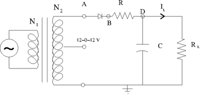
1.)Consider building circuit below.
Determine the components needed in order to make the output ripple have a less than 1 Volt.
The output ripple can be found by
I have used the following components and input parameters:
which corresponds to 60 Hz
The current through the circuit can be found as
where {math}R_{tot} = R + \frac{R_L \cdot \frac{1}{j\omega C}}{R_L + \frac{1}{j\omega C}}{/math}
So my output ripple becomes </math>\Delta V = \frac{}{}</math>
List the components below and show your instructor the output observed on the scope and sketch it below.
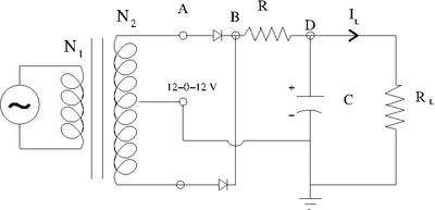
Full-Wave Rectifier Circuit
Determine the components needed in order to make the above circuit's output ripple have a less than 0.5 Volt.
List the components below and show your instructor the output observed on the scope and sketch it below.
Go Back to All Lab Reports Forest_Electronic_Instrumentation_and_Measurement

