Difference between revisions of "TF EIM Chapt3"
Jump to navigation
Jump to search
| Line 19: | Line 19: | ||
The voltage changes in between point <math>a</math> and DC are passed according to what you select for the break frequency (<math>\omega_B = \frac{1}{RC}</math>) | The voltage changes in between point <math>a</math> and DC are passed according to what you select for the break frequency (<math>\omega_B = \frac{1}{RC}</math>) | ||
| + | |||
| + | In the above pulse picture it was assumed that \tau >> \frac{1}{\omega_B} | ||
=Integrator= | =Integrator= | ||
Revision as of 17:38, 8 February 2011
Differentiator circuit
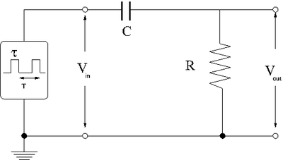
Consider the effect of a low-pass filter on a rectangular shaped input pulse with a width and period .
The first thing to consider is what happens to the different parts of the square pulse as it travels to the circuit.
You know that the circuit, as a high pass filter, will tend to attenuate low frequency (slow changing) voltages and not high frequency (quick changing) voltages.
This means no DC voltage values pass beyond the capacitor.
This means that points and in the pulse shown below should pass through the circuit.
The voltage changes in between point and DC are passed according to what you select for the break frequency ()
In the above pulse picture it was assumed that \tau >> \frac{1}{\omega_B}


