Difference between revisions of "TF EIM Chapt3"
Jump to navigation
Jump to search
| Line 53: | Line 53: | ||
[[File:TF_EIM_BandWidthDef_LC.gif | 200 px]] | [[File:TF_EIM_BandWidthDef_LC.gif | 200 px]] | ||
| + | |||
| + | ;Quality Factor | ||
| + | :The Quality factor for this circuit may be expressed in term of the bandwidth such that | ||
| + | ::<math>Q=\frac{\omega_0}{BW}=\frac{\omega_0}{\Delta \omega}</math> | ||
[[Forest_Electronic_Instrumentation_and_Measurement]] | [[Forest_Electronic_Instrumentation_and_Measurement]] | ||
Revision as of 06:02, 2 February 2011
gain
Loop Theorem
or
- Notice
- When then the AC signal is attenuated.
Looking at the Voltage divider aspect of the circuit
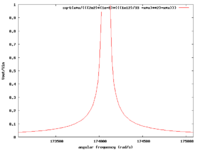
| and and R=200 |

|
| rad/s or Hz |
Q and Bandwidth
In the above circuit
The inductors reactance at this resonance frequency is
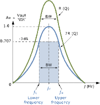
- Bandwith
- The most common definition for the Bandwidth of this circuit is the frequency range over which the output decreases by 3 dB. This correspond to the frequency at which the circuits power is cut in half from the resonance frequency.
- Quality Factor
- The Quality factor for this circuit may be expressed in term of the bandwidth such that
