Difference between revisions of "Lab 5 RS"
Jump to navigation
Jump to search
| Line 6: | Line 6: | ||
[[File:TF_EIM_Lab5_LC.png| 200 px]] | [[File:TF_EIM_Lab5_LC.png| 200 px]] | ||
#Design a '''parallel''' LC resonant circuit with a resonant frequency between 50-200 kHz. use <math>L</math> = 10 - 100 <math>\mu H</math>. | #Design a '''parallel''' LC resonant circuit with a resonant frequency between 50-200 kHz. use <math>L</math> = 10 - 100 <math>\mu H</math>. | ||
| + | |||
#Construct the LC circuit using a non-polar capacitor | #Construct the LC circuit using a non-polar capacitor | ||
#Measure the Gain <math>\equiv \frac{V_{out}}{V_{in}}</math> as a function of frequency. (20 pnts) | #Measure the Gain <math>\equiv \frac{V_{out}}{V_{in}}</math> as a function of frequency. (20 pnts) | ||
Revision as of 04:49, 1 February 2011
- LC Resonance circuits
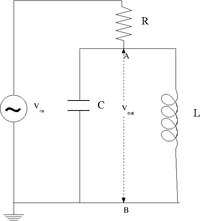
The LC cicuit
- Design a parallel LC resonant circuit with a resonant frequency between 50-200 kHz. use = 10 - 100 .
- Construct the LC circuit using a non-polar capacitor
- Measure the Gain as a function of frequency. (20 pnts)
- Measure the Gain when an external resistance approximately equals to the inherent resistance of the rf choke . (20 pnts)
- Compare the measured and theoretical values from the resonance frequency () and the Quality factor value for each case; . (10 pnts)
Questions
- If r=0, show that . (10 pnts)
- Show that at resonance. (10 pnts)
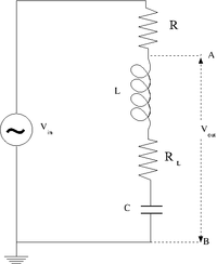
The LRC cicuit
- Design and construct a series LRC circuit.
- Measure and Graph the Gain as a function of the oscillating input voltage frequency. (20 pnts)
Questions
- What is the current at resonance? (5 pnts)
- What is the current as ? (5 pnts)
Forest_Electronic_Instrumentation_and_Measurement Go Back to All Lab Reports

