Difference between revisions of "NEUPRFP 2009"
m (Protected "NEUPRFP 2009" ([edit=autoconfirmed] (indefinite) [move=autoconfirmed] (indefinite) [read=autoconfirmed] (indefinite))) |
|||
| (24 intermediate revisions by the same user not shown) | |||
| Line 3: | Line 3: | ||
A PDF version of the RFP is given below | A PDF version of the RFP is given below | ||
| − | [[ | + | [[Image:NEUP_RFP_2008.pdf]] |
| + | |||
| + | Our Proposal | ||
;Proposal Due date: 11:59 am March 16,2009 | ;Proposal Due date: 11:59 am March 16,2009 | ||
| Line 48: | Line 50: | ||
(D.Dale) | (D.Dale) | ||
| − | This project involves the investigation of nuclear photofission at a fundamental level. Its primary goals are to (1) ascertain | + | This project involves the investigation of nuclear photofission at a fundamental level. Its primary goals are to |
| + | |||
| + | (1) ascertain | ||
if the angular distribution of fission fragments from active interrogation of linearly polarized photons will result in a signature | if the angular distribution of fission fragments from active interrogation of linearly polarized photons will result in a signature | ||
| − | in the form of easily detected neutron asymmetries, and if so, (2) evaluate the potential for utilization of this phenomenon in the areas of materials control and accountability | + | in the form of easily detected neutron asymmetries, and if so, |
| + | |||
| + | some reviewers in the past have misinterpreted proposals thinking they were | ||
| + | going to detect the fission fragments. We should reduce this risk as | ||
| + | much as possible. How about the following sentence to replace the one above | ||
| + | |||
| + | measure the asymmetric neutron emission resulting from anisotropic fission | ||
| + | fragment emission when actinides are actively interrogation using linearly polarized photons | ||
| + | |||
| + | (2) evaluate the potential for utilization of this phenomenon in the areas of materials control and accountability | ||
and as a technique to quantify actinides for safeguards and quality control applications. The method for the production of linearly polarized | and as a technique to quantify actinides for safeguards and quality control applications. The method for the production of linearly polarized | ||
photons from a bremsstrahlung beam described in this proposal is well established and can be readily implemented as an add on to other | photons from a bremsstrahlung beam described in this proposal is well established and can be readily implemented as an add on to other | ||
| − | systems using bremsstrahlung beams for active interrogation. The fundamental measurements of the dependencies of the fission fragment angular distributions | + | systems using bremsstrahlung beams for active interrogation. |
| − | and their expected manifestation in the neutron angular distributions, however, constitute a new, previously unexplored area of investigation. | + | |
| + | Change | ||
| + | The fundamental measurements of the dependencies of the fission fragment angular distributions | ||
| + | and their expected manifestation in the neutron angular distributions, however, | ||
| + | constitute a new, previously unexplored area of investigation. | ||
| + | |||
| + | To | ||
| + | |||
| + | The fundamental measurements of the neutron angular distributions, a result of the | ||
| + | fission fragment angular distributions, | ||
| + | constitutes a new, previously unexplored area of investigation. | ||
==Proposed scope description and Scientific Merit (20%)== | ==Proposed scope description and Scientific Merit (20%)== | ||
| Line 89: | Line 112: | ||
E). \\ | E). \\ | ||
| − | |||
| − | |||
| − | |||
| − | |||
| − | |||
| − | |||
| − | |||
| − | |||
| − | |||
| − | |||
| − | |||
| − | |||
| − | |||
| − | |||
| − | |||
| − | |||
| − | |||
| − | |||
| − | |||
| Line 293: | Line 297: | ||
| − | [[Image: | + | [[Image:hrrl-1.jpg|thumb|hrrl]] |
Neutrons will be identified via the time of flight method, with the start signal coming from the accelerator beam pulse. | Neutrons will be identified via the time of flight method, with the start signal coming from the accelerator beam pulse. | ||
| Line 328: | Line 332: | ||
\end{thebibliography} | \end{thebibliography} | ||
| + | (D.Dale) | ||
| − | == | + | ==Milestones== |
| − | + | 12 months: Acquire and assemble instrumentation-(vacuum pipe for electron | |
| + | beam dump, beam dump magnet, exit window/pair converter, radiator, four PMTs + bases, octal | ||
| + | discriminators, 4-fold logic unit) | ||
| − | + | 24 months: commission experimental setup, begin measurements | |
| − | + | 36 months: report on measurements with application assessment | |
| − | |||
| + | ==Timeline and Deliverables== | ||
The proposed work plan for this project is as follows: | The proposed work plan for this project is as follows: | ||
| Line 344: | Line 351: | ||
\begin{itemize} | \begin{itemize} | ||
| − | \item{} | + | \item{} month 6: Develop beam diagnostics including two view screens for monitoring the position and angle of the electron beam, and a pair spectrometer photon flux monitor consisting of a converter target, dipole magnet, and plastic scintillation detector. |
| − | \ | + | \item{} month 12: Establish beamline for linearly polarized photons. This will consist of the installation of a new vacuum system, a remotely removeable bremsstrahlung radiator, coil deflector magnets to deflect the beam up and down two degrees to vary the photon beam polarization, and an off axis photon beam collimator.\\ |
| − | \item{} Verify the production of linearly polarized beam using the high | + | \item{}month 20: Verify the production of linearly polarized beam using the high |
analyzing power of the photodisintegration of the deuteron. Here, we will measure the azimuthal dependence of the neutron yields from deuterated water targets. Backgrounds will be directly measured using and identical setup except with an $H_2O$ target. | analyzing power of the photodisintegration of the deuteron. Here, we will measure the azimuthal dependence of the neutron yields from deuterated water targets. Backgrounds will be directly measured using and identical setup except with an $H_2O$ target. | ||
| − | \item{}Measure neutron azimuthal asymmetries for actinides as a function of target, bremsstrahlung endpoint energy, and neutron energy. | + | \item{}month 24: Measure neutron azimuthal asymmetries for actinides as a function of target, bremsstrahlung endpoint energy, and neutron energy. |
| − | \item{}Measure neutron azimuthal asymmetries for a variety of other targets to investigate the possibility of false positives. | + | \item{}month 30: Measure neutron azimuthal asymmetries for a variety of other targets to investigate the possibility of false positives. |
| − | \item{}Assemble an overall assessment of the effectiveness of the technique for safeguards applications. | + | \item{}month 34: Assemble an overall assessment of the effectiveness of the technique for safeguards applications. |
| − | \item{}Publish the results. | + | \item{}month 36: Publish the results. |
\end{itemize} | \end{itemize} | ||
| − | |||
| − | |||
| − | |||
| − | |||
| − | |||
| − | |||
| − | |||
| − | |||
| − | |||
| − | |||
| − | |||
| − | |||
| − | |||
| − | |||
| − | |||
| − | |||
| − | |||
| − | |||
| − | |||
| − | |||
==R&D resources and Capabilities (10%)== | ==R&D resources and Capabilities (10%)== | ||
| Line 389: | Line 376: | ||
The linac shown in Figure~\ref{fig:hrrl) is capable of accelerating electrons up to energies of 16 MeV. The electrons are transported in pulse trains having a minimum width of 25 ns and a maximum repetition rate of 1 kHz. The accelerator can produce 80 mA peak currents which can intersect a radiator target to produce bremsstrahlung photons. The bremsstrahlung photons enter an experimental cell through a collimator configured to select off axis polarized photons. A target, in the experimental cell, is positioned in the path of the polarized photons. | The linac shown in Figure~\ref{fig:hrrl) is capable of accelerating electrons up to energies of 16 MeV. The electrons are transported in pulse trains having a minimum width of 25 ns and a maximum repetition rate of 1 kHz. The accelerator can produce 80 mA peak currents which can intersect a radiator target to produce bremsstrahlung photons. The bremsstrahlung photons enter an experimental cell through a collimator configured to select off axis polarized photons. A target, in the experimental cell, is positioned in the path of the polarized photons. | ||
| − | Particle detection systems are placed at predetermined locations in the experimental cell to measure the reactants emanating from the target. The authors of this proposal performed a previous photofission experiment using two neutron sensitive scintillators place at 90 degrees to the incident photon beam and in the same plane as a 20 cm long target of heavy water (D2O). A NaI crystal optically coupled to a photomultiplier tube (PMT) was placed off the beam line axis at the end of the experimental cell to monitor the incident photon flux. The photomultiplier signals were amplified by Ortec Model 672 amplifiers and discriminated using a CAEN constant fraction discrimiator model N842. The NaI detector output was sent directly to a sampling ADC manufactured by FAST~\cite{ | + | Particle detection systems are placed at predetermined locations in the experimental cell to measure the reactants emanating from the target. The authors of this proposal performed a previous photofission experiment using two neutron sensitive scintillators place at 90 degrees to the incident photon beam and in the same plane as a 20 cm long target of heavy water (D2O). A NaI crystal optically coupled to a photomultiplier tube (PMT) was placed off the beam line axis at the end of the experimental cell to monitor the incident photon flux. The photomultiplier signals were amplified by Ortec Model 672 amplifiers and discriminated using a CAEN constant fraction discrimiator model N842. The NaI detector output was sent directly to a sampling ADC manufactured by FAST~\cite{FAST7070ADC} while the neutron detector outputs were send to a time to amplitude converter (ORTEC 567, 566). The TAC output is proportional to the neutron time of flight and was measured with the ADCs manufactured by FAST~\cite{FAST7070ADC}. A data acquisition system based on MPA-3 ~\cite{MPA-3} recorded the measurements for analysis. Figure~\ref{fig:n_ToF} shows a sample Time of Flight (ToF) spectrum from the neutron sensitive detectors. The spectrum illustrates the apparatus' ability to identify particles with flight times consistent with photons and distinguish them from particles with flight times consistent with neutrons. |
| − | \ | + | \bibitem{MPA-3} Fast ComTec GmbH, Grunwalder Weg 28a, D-82041 Oberhaching Germany |
| − | \ | + | \bibitem{FAST7070ADC} http://www.fastcomtec.com/products/product-lines/nim-modules/7070.html |
| − | \ | + | \bibitem{ORTEC567TAC}http://www.ortec-online.com/electronics/tac/567.htm |
| − | \ | + | \bibitem{ORTEC672Amp}http://www.ortec-online.com/electronics/amp/672.htm |
\begin{figure}[ht] | \begin{figure}[ht] | ||
| Line 458: | Line 445: | ||
==Quality Assurance== | ==Quality Assurance== | ||
| − | + | The procedures used to carry out this research and the results obtained will be documented in refereed journals. In addition, full documentation will be | |
| − | + | recorded in graduate student theses and dissertations. | |
| + | Laboratory notebooks will be maintained throughout the project and will be available for inspection by the funding agency at any time. | ||
| + | |||
| Line 465: | Line 454: | ||
=Budget form= | =Budget form= | ||
| + | Materials and supplies: 26k | ||
| − | + | 4 PMT - 5k | |
| − | + | beam pipe - 15k | |
| − | + | collimator - 5k | |
| + | scintillators - 1k | ||
= Proposal Graphs= | = Proposal Graphs= | ||
[[Image:ToF_H20r199_D20r229.gif| thumb| The time of flight measured by detector A. The unhatched histogram represents the flight time observed when a D2O target is used while the hatched histogram is observed when using the H2O target]] | [[Image:ToF_H20r199_D20r229.gif| thumb| The time of flight measured by detector A. The unhatched histogram represents the flight time observed when a D2O target is used while the hatched histogram is observed when using the H2O target]] | ||
| + | [[Image:ToF_H20r194_D20r234.gif| thumb| The time of flight measured by detector A. The green histogram represents the flight time observed when a D2O target is used while the blue histogram is observed when using the H2O target]] | ||
| Line 479: | Line 471: | ||
[[Image:pol.jpg|thumb|pol]] | [[Image:pol.jpg|thumb|pol]] | ||
| + | |||
| + | [[Image:val2.jpg|400px]] | ||
| + | |||
| + | [[Image:val1.jpg|400px]] | ||
| + | |||
| + | = Proposal V1 = | ||
| + | |||
| + | [[NEUP_2009_V1]] | ||
Latest revision as of 02:01, 31 December 2010
Photofission of Actinides with Linearly Polarized Photons
A PDF version of the RFP is given below
Our Proposal
- Proposal Due date
- 11:59 am March 16,2009
- 3/4/09
- preproposal + Budget to dave harris
- 3/10/09
- first draft
- 3/13/09
- final version (of course not Dan's working the weekend)
10 page narrative
Guidelines
Go/NoGo requirements
- Commitment to reporting
- If DOE Lab Work and safety Health program
- Export Control
- Standard Research Subcontract
- Quality Assurance if non-academic partner
- commitment to prepare additional contracts
Proposal Outline
Title: \begin{center} {\bf \Large Photofission of Actinides with Linearly Polarized Photons}\\ Technical Workscope : AFS-2 \end{center}
Technical Work Scope and Mission Relevance (20%)
(D.Dale)
This project involves the investigation of nuclear photofission at a fundamental level. Its primary goals are to
(1) ascertain if the angular distribution of fission fragments from active interrogation of linearly polarized photons will result in a signature in the form of easily detected neutron asymmetries, and if so,
some reviewers in the past have misinterpreted proposals thinking they were
going to detect the fission fragments.  We should reduce this risk as
much as possible.  How about the following sentence to replace the one above
 measure the asymmetric neutron emission resulting from anisotropic fission
fragment emission when actinides are actively interrogation using linearly polarized photons
(2) evaluate the potential for utilization of this phenomenon in the areas of materials control and accountability and as a technique to quantify actinides for safeguards and quality control applications. The method for the production of linearly polarized photons from a bremsstrahlung beam described in this proposal is well established and can be readily implemented as an add on to other systems using bremsstrahlung beams for active interrogation.
Change
The fundamental measurements of the dependencies of the fission fragment angular distributions
and their expected manifestation in the neutron angular distributions, however,
constitute a new, previously unexplored area of investigation.
To
The fundamental measurements of the neutron angular distributions, a  result of the
fission fragment angular distributions,
constitutes a new, previously unexplored area of investigation.
Proposed scope description and Scientific Merit (20%)
(D.Dale)
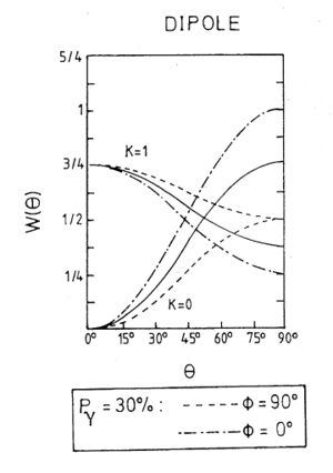
For linearly polarized photons and considering only electric dipole (E1) transitions, the photofission of an even-even nucleus ($J^{\pi} = 0^+$, such as $^{238}U$) gives the angular distribution of the fission fragments \cite{Geissen1982}:
\begin{equation}
\end{equation}
The angular distribution coefficients $A_o$ and $A_2$ depend on the
transition
state (J,K), where is the projection of the total spin $J$ on the
symmetry axis of the deformed nucleus. For $J = 1, K = 0$, we have
$A_o = 1/2, A_2 = -1/2$ and for $J = 1, K = 1$, we have $A_o = 1/2, A_2 =
1/4$.
$P_2 = \frac{1}{2}(2 - 3 sin2 \theta)$, $P_{\gamma}$ is the
photon polarization, and $f_2(1,1) = 3 sin2 \theta$. $\theta$ is the
polar
angle with respect to the beam and $\phi$ is the azimuthal angle ($\phi =
0$
parallel to the electric field vector and $\phi = \pi/2$ perpendicular to
E). \\
For any target thicker than a few $mg/cm2$, of course, the fission fragments are not detectable. The question we wish to address here concerns whether or not the angular asymmetry in the fission fragments is manifest in the angular distribution of the prompt neutrons which they emit, thus providing a possible signature for the presence of photofission. \\
To a very good approximation, the recoiling fission fragments emit neutrons isotropically in their center of mass\cite{Ploeg95}. A fully accelerated fission fragment travels with a speed of about 4\% of the speed of light. In the center of mass of the fragment, a typical 1 MeV neutron travels with a $\beta$ of about $4.6$\% of $c$. Thus, the neutron energy spectrum measured in the laboratory is a convolution of the "primordial" spectrum which the excited fission fragment emits, and the kinematical effects due to the fragment recoil. \\
These effects were examined under the following assumptions:
\begin{itemize}
\item{}The fission fragment mass distribution was sampled uniformly between $85<A<105$ and $130<A<150$.
\item{}A fixed amount of total kinetic energy, 175 MeV, is given to the two fission fragments.
\item{}Neutrons are emitted isotropically in the center of mass of the fully accelerated fission fragments with an energy distribution given by:
\begin{equation} N(E) = \sqrt{E} exp(-E/0.75) \end{equation}
This reproduces the fission laboratory neutron energy distribution as measured with $(n,f)$.
\item{}The fission fragment angular distribution is sampled in both
$\theta$ and $\phi$ as noted above
for either K = 0 or K = 1, and the neutrons were given the appropriate
kinematic boost.
\item{}The resulting rate asymmetry $\frac{N(\theta = \pi/2 ,\phi = 0)}{N(\theta = \pi/2,\phi = \pi/2)}$ is calculated for $P_{\gamma} = 0.3$. This degree of polarization is commensurate with that attainable by using off axis bremsstrahlung, as described below.
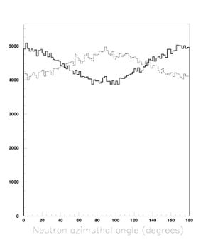
For a pure $K = 0$ transition, the resulting $\phi$ distribution is shown in the figure~\ref{fig:k0k1}. The resulting rate asymmetry, $\frac{N(\theta = \pi/2,\phi = 0)}{N(\theta = \pi/2,\phi = \pi/2)}$ is 1.25, reflecting the angular distribution of the fission fragments as well as the "washing out" effect of the neutrons emitted isotropically in the frame of the fission fragment. This asymmetry is for the case in which there is no cut on the neutron energy. If one imposes the cut $E_n > 2$ MeV in the simulation, the asymmetry rises to 1.37. For the pure $K = 1$ case, the resulting $\phi$ distribution is also shown in figure~\ref{fig:k0k1}. The corresponding rate asymmetry in this case is 0.84 without any neutron energy cut.
\begin{figure}
\vspace*{-0.5in}
\begin{center}
\begin{minipage}[t]{0.58\linewidth}
\epsfig{file=k0k1.eps,width=\linewidth}
\end{minipage}\hfill
\begin{minipage}[t]{0.38\linewidth}
\vspace*{-5cm}\caption{Monte Carlo $\phi$ distribution of neutrons at
$\theta = 90^{\circ}$. Solid: $K = 0$. Dashed: $K= 1$.}
\label{fig:k0k1}
\end{minipage}
\end{center}
\end{figure}
These asymmetries are merely representative of what one {\em might} observe. In the measurements proposed here, fission in actinides will be induced by a bremsstrahlung beam of continuous energy. In practice, fission may proceed via multiple channels, and one cannot directly calculate the expected neutron asymmetries. As such, we propose a complete experimental investigation of the $\theta$ and $\phi$ distributions of the neutron yields for a number of actinides to ascertain the magnitude of the asymmetries and to determine the sensitivity of the technique. \\
{\bf Proposed production of linearly polarized photons at the IAC}\\
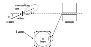
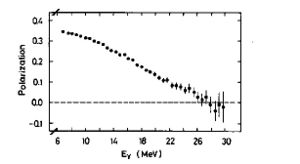
As described in the {\em Facilities} section of this proposal, the experimenters have ready access to a number of low energy (10's of MeV) electron linacs. We propose to construct a beamline for the production of linearly polarized bremsstrahlung photons modeled after that constructed by the Geissen group. It is well known that when an electron beam strikes a thin radiator, the resulting bremsstrahlung radiation which lies off axis from the incident beam is polarized as shown in figure \ref{fig:offaxisc}. If one collimates the photon beam at an angle of $\theta = \frac{m_e}{Ee}$ where $m_e$ is the rest mass of the electron and $E_e$ is the energy of the incident beam, the polarization is maximized. A schematic of the relevant geometry is shown in the figure. The energy dependence of the polarization of such a beam, as measured by a polarimeter which is based on the large analyzing power of the photodisintegration of the deuteron, is shown in figure \ref{fig:pol} where it can be seen that modest polarizations of the bremsstrahlung beam can be obtained. The rate of the photons as compared to the uncollimated case is decreased by approximately a factor of 20 to 30 due to the collimation as well as the need for a thin radiator to minimize multiple scattering of the incident electrons.
\begin{figure}[ht]
\centering
\psfig{figure=offaxisc.eps,height=5.in,width=7.in}
\caption{Production of linearly polarized bremsstrahlung photons by the off axis technique.}
\label{fig:offaxisc}
\end{figure}
\begin{figure}[ht] \centering \psfig{figure=pol.eps,height=5.in,width=7.in} \caption{Polarization as a function of photon energy for the off axis bremsstrahlung production of linearly polarized photons. Figure is from \cite{Geissen1987}.} \label{fig:pol} \end{figure}
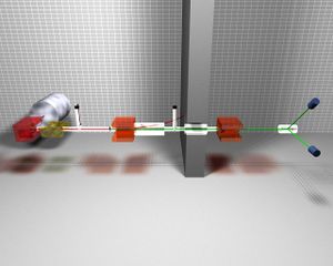
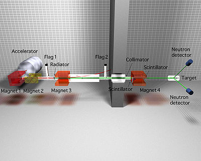
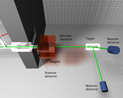
We propose to construct such a linearly polarized bremsstrahlung beamline and a polarimeter to measure its performance. This facility will be used to measure the angular dependence of the photofission neutron yields as a function of both the bremsstrahlung endpoint energy and the neutron energy to evaluate the sensitivity of this technique to the presence of photofission events. A schematic of the proposed experimental setup is shown in figure \ref{fig:hrrl}. It consists of a pulsed electron accelerator delivering approximately 14 MeV electrons which are bent 90 degress in the horizontal plane. The electrons are then bent up or down in the vertical plane approximately two degrees before they strike a thin bremsstrahlung converter. A fixed collimator is placed downstream of the bremmstrahlung radiator and is offset in the horizontal plane. This collimator passes bremstrahlung photons which are off axis from the primary electron beam, and therefore are linearly polarized 45 degrees with respect to the horizontal, with an orientation depending upon the angle of incidence of the electron beam on the bremsstrahlung radiator. Between the radiator and the collimator, a magnet deflects charged particles in the horizontal plane away from the photon collimator. The photons exit the vacuum via a thin window at the downstream edge of the collimator. This window serves a a thin converter for a pair spectrometer luminosity monitor which is used for relative normalization of flux in the two polarization states. In addition to the converter, the pair spectrometer consists of a 0.35 T, 20 cm dipole magnet and two plastic scintillator detectors to measure the electrons and positrons in coincidence. Downstream of the pair spectrometer will be the target. When polarimetry experiments are being performed, this target will consist of $D_2O$ and during production runs will generally be a solid actinide target. A plastic scintillator neutron detector will be placed at an angle of 90 degrees with respect to the beam, at a 45 degree angle from the horizontal plane. This detector will measure the neutron yields as a function of the orientation of the polarization. A second detector will be placed at a 90 degree angle with respect to the beam in the horizontal plane. The purpose of this detector will be to monitor the setup for false asymmetries.
\begin{figure}[ht]
\centering
\psfig{figure=Hrrl_valeriia_1.eps,height=5.in,width=7.in}
\caption{A schematic of the proposed experimental setup.}
\label{fig:hrrl}
\end{figure}
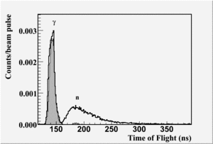
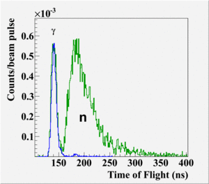
Neutrons will be identified via the time of flight method, with the start signal coming from the accelerator beam pulse. In October 2008, a test run was performed with a deuterated water target and the results are shown in figure \ref{fig:tony}, where the neutron time of flight peak can be clearly distinguished from the photon flash. Furthermore, the neutron peak is greatly reduced when the target is $H_2O$.
\begin{figure}[ht] \centering \psfig{figure=tony.eps,height=5.in,width=7.in} \caption{Neutron time of flight spectra for $D_2O$ and $H_2O$ targets.} \label{fig:tony} \end{figure}
Bibliography
\section{Bibliography}
\begin{thebibliography}{99}
\bibitem{Geissen1982}R. Ratzek, {\em et al.} Z. Phys. A -- Atoms and Nuclei 308, 63-71 (1982).
\bibitem{Geissen1987}U.E.P. Berg and Ulrich Kneissl, Ann. Rev. Nucl. Part. Sci. 37, 33-69 (1987).
\bibitem{Ploeg95}H. van der Ploeg {\em et al.}, Phys. Rev. C, 52, no. 4 (1995).
\bibitem{gpnp}M.P. De Pascale, {\em et al.}, Phys. Rev. C, 32, no. 6 (1985).
\end{thebibliography} (D.Dale)
Milestones
12 months: Acquire and assemble instrumentation-(vacuum pipe for electron beam dump, beam dump magnet, exit window/pair converter, radiator, four PMTs + bases, octal discriminators, 4-fold logic unit)
24 months: commission experimental setup, begin measurements
36 months: report on measurements with application assessment
Timeline and Deliverables
The proposed work plan for this project is as follows:
\begin{itemize}
\item{} month 6: Develop beam diagnostics including two view screens for monitoring the position and angle of the electron beam, and a pair spectrometer photon flux monitor consisting of a converter target, dipole magnet, and plastic scintillation detector.
\item{} month 12: Establish beamline for linearly polarized photons. This will consist of the installation of a new vacuum system, a remotely removeable bremsstrahlung radiator, coil deflector magnets to deflect the beam up and down two degrees to vary the photon beam polarization, and an off axis photon beam collimator.\\
\item{}month 20: Verify the production of linearly polarized beam using the high analyzing power of the photodisintegration of the deuteron. Here, we will measure the azimuthal dependence of the neutron yields from deuterated water targets. Backgrounds will be directly measured using and identical setup except with an $H_2O$ target.
\item{}month 24: Measure neutron azimuthal asymmetries for actinides as a function of target, bremsstrahlung endpoint energy, and neutron energy.
\item{}month 30: Measure neutron azimuthal asymmetries for a variety of other targets to investigate the possibility of false positives.
\item{}month 34: Assemble an overall assessment of the effectiveness of the technique for safeguards applications.
\item{}month 36: Publish the results.
\end{itemize}
R&D resources and Capabilities (10%)
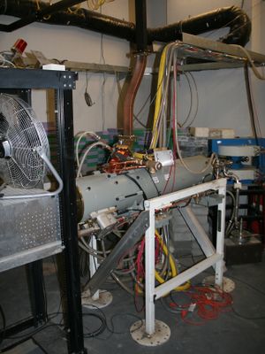
The research and development resources to support this proposal include an in house electron accelerator, several particle detector systems, and signal processing electronics. The linac shown in Figure~\ref{fig:hrrl) is capable of accelerating electrons up to energies of 16 MeV. The electrons are transported in pulse trains having a minimum width of 25 ns and a maximum repetition rate of 1 kHz. The accelerator can produce 80 mA peak currents which can intersect a radiator target to produce bremsstrahlung photons. The bremsstrahlung photons enter an experimental cell through a collimator configured to select off axis polarized photons. A target, in the experimental cell, is positioned in the path of the polarized photons.
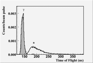
Particle detection systems are placed at predetermined locations in the experimental cell to measure the reactants emanating from the target. The authors of this proposal performed a previous photofission experiment using two neutron sensitive scintillators place at 90 degrees to the incident photon beam and in the same plane as a 20 cm long target of heavy water (D2O). A NaI crystal optically coupled to a photomultiplier tube (PMT) was placed off the beam line axis at the end of the experimental cell to monitor the incident photon flux. The photomultiplier signals were amplified by Ortec Model 672 amplifiers and discriminated using a CAEN constant fraction discrimiator model N842. The NaI detector output was sent directly to a sampling ADC manufactured by FAST~\cite{FAST7070ADC} while the neutron detector outputs were send to a time to amplitude converter (ORTEC 567, 566). The TAC output is proportional to the neutron time of flight and was measured with the ADCs manufactured by FAST~\cite{FAST7070ADC}. A data acquisition system based on MPA-3 ~\cite{MPA-3} recorded the measurements for analysis. Figure~\ref{fig:n_ToF} shows a sample Time of Flight (ToF) spectrum from the neutron sensitive detectors. The spectrum illustrates the apparatus' ability to identify particles with flight times consistent with photons and distinguish them from particles with flight times consistent with neutrons.
\bibitem{MPA-3} Fast ComTec GmbH, Grunwalder Weg 28a, D-82041 Oberhaching Germany
\bibitem{FAST7070ADC} http://www.fastcomtec.com/products/product-lines/nim-modules/7070.html
\bibitem{ORTEC567TAC}http://www.ortec-online.com/electronics/tac/567.htm
\bibitem{ORTEC672Amp}http://www.ortec-online.com/electronics/amp/672.htm
\begin{figure}[ht] \centering \psfig{figure=hrrl.eps,height=5.in,width=7.in} \caption{} \label{fig:hrrl} \end{figure}
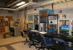
\begin{figure}[ht]
\centering
\psfig{figure=countroom.eps,height=5.in,width=7.in}
\caption{}
\label{fig:countroom}
\end{figure}
(V.S.- pictures + T.Forest - description)
CUT ALL THIS, NO? (DD)
Yes! or Move (TF)
Idaho State University and the Idaho Accelerator Center have a number of electron linacs capable of generating
milliamp beams of electrons with energies up  to 40 MeV.
Our proposed beamline for the production of linearly
polarized
bremsstrahlung
photons will be modeled after that of the Geissen group\cite{Geissen87}.
We propose to
construct such a linearly polarized bremsstrahlung beamline and a
polarimeter
to measure its performance,
and to measure the angular dependence of
the photofission
neutron yields as a function of both the bremsstrahlung endpoint
energy and the neutron energy (as determined by time of flight)
to evaluate the sensitivity of this technique to the
presence of photofission events.
Roles of Participants and Team Qualifications (15% or 2 pages)
Participant A = D.Dale = Manager Photofission physics
Participant B = V. Starovoitova = Data analysis expert
Participant C = T. Forest = DAQ, beam line design
Participant D = P. Cole = beamline instrumentation, expert complainer
Students = 2 PhD theses + 2 MS theses, 2 undergrad training
Work Scope Challenges and expected innovations
(B.S)
Quality Assurance
The procedures used to carry out this research and the results obtained will be documented in refereed journals. In addition, full documentation will be recorded in graduate student theses and dissertations. Laboratory notebooks will be maintained throughout the project and will be available for inspection by the funding agency at any time.
- 10 pages
Budget form
Materials and supplies: 26k
4 PMT - 5k beam pipe - 15k collimator - 5k scintillators - 1k
Proposal Graphs
