Difference between revisions of "FC Analysis"
Jump to navigation
Jump to search
| (100 intermediate revisions by the same user not shown) | |||
| Line 1: | Line 1: | ||
| − | [[File: | + | [http://wiki.iac.isu.edu/index.php/PhotoFission_with_Polarized_Photons_from_HRRL Go Back] |
| − | [[File: | + | |
| + | =FC analysis using ADC channel current distribution= | ||
| + | For each ADC channel: | ||
| + | <math> ADCSum^{channel}=\sum_{i=1}^{pulses}{ADC_{pulse}^{channel}}</math><br> | ||
| + | <math> ADCErr^{channel}=\sqrt{\frac{\sum_{i=1}^{pulses}{ADC_{pulse}^{channel}}}{pulses}}</math><br> | ||
| + | |||
| + | For distribution over all ADC channel: | ||
| + | <math> ADC^{avg}=\frac{\sum_{i=1}^{16}{ADCSum^{channel}*i}}{\sum_{i=1}^{16}{ADC_{i}}}</math><br> | ||
| + | <math> ADC^{err}=\frac{\sum_{i=1}^{16}{ADCErr^{channel}*i}}{\sum_{i=1}^{16}{ADC_{i}}}</math><br> | ||
| + | |||
| + | |||
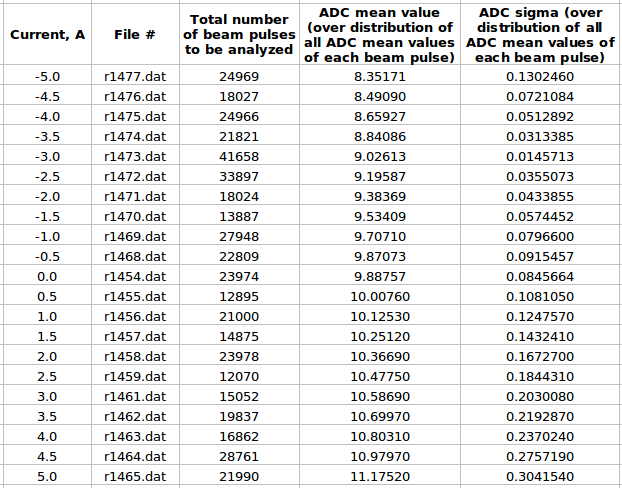
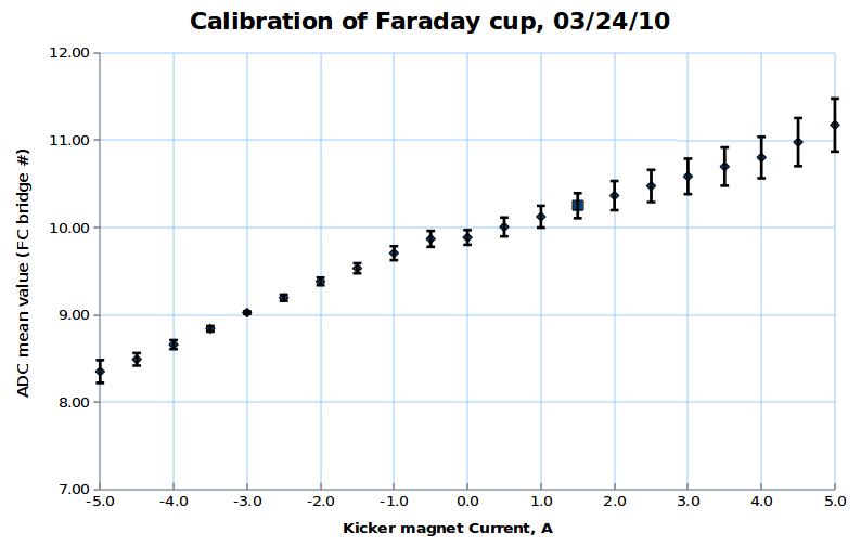
| + | =FC analysis using pulse by pulse ADC channel mean value distribution= | ||
| + | |||
| + | For each beam pulse: | ||
| + | <math> ADC^{avg}_{pulse}=\frac{\sum_{i=1}^{16}{ADC_{i}*i}}{\sum_{i=1}^{16}{ADC_{i}}}</math> | ||
| + | |||
| + | For distribution over all beam pulses: | ||
| + | <math> ADC^{avg}=\frac{\sum_{i=1}^{pulses}{ADC^{avg}_{pulse}}}{pulses}</math><br> | ||
| + | <math> ADC^{err}={ \sqrt{\frac{1}{pulses}\sum_{i=1}^{pulses}{\left(ADC^{avg}_{pulse} - ADC^{avg}\right)^{2}}}}</math> | ||
| + | |||
| + | Here is:<br> | ||
| + | 1. ADC# = bridge#<br> | ||
| + | 2. Pulse# = ReadOut# = Entry# = Event# | ||
| + | |||
| + | [[File:FC_data_23.png]]<br><br> | ||
| + | [[File:FC_plot_2_4.png]] | ||
| + | |||
| + | <br><br>Some examples of ADC mean value distribution. Here are:<br> | ||
| + | 1. x axis: ADC mean value for one pulse<br> | ||
| + | 2. y axis: number of pulse w/ that ADC mean value<br> | ||
| + | [[File:1477_1.png]][[File:1473_1.png]]<br> | ||
| + | [[File:1461_1.png]][[File:1465_1.png]]<br><br> | ||
| + | |||
| + | =3D Faraday cup plot= | ||
| + | Below is the plot of the charge in Faraday cup (pC) as a function of magnet current (vertical axis, A) (basically magnetic field) and ADC (horizontal axis). | ||
| + | |||
| + | [[File:Far.jpg]] | ||
| + | |||
| + | =Faraday cup ADC channel distribution= | ||
| + | =Faraday cup rain= | ||
| + | |||
| + | |||
| + | [http://wiki.iac.isu.edu/index.php/FC_Analysis Go Up] | ||
Latest revision as of 03:57, 5 April 2010
FC analysis using ADC channel current distribution
For each ADC channel:
For distribution over all ADC channel:
FC analysis using pulse by pulse ADC channel mean value distribution
For each beam pulse:
For distribution over all beam pulses:
Here is:
1. ADC# = bridge#
2. Pulse# = ReadOut# = Entry# = Event#
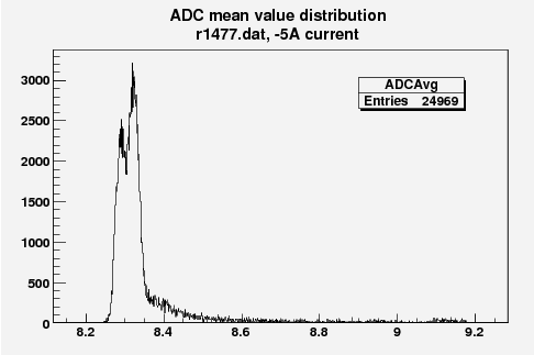
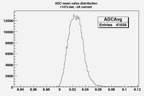
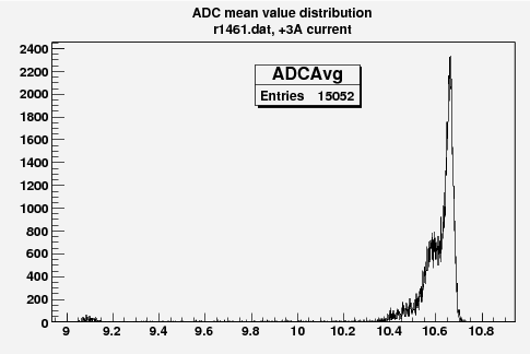
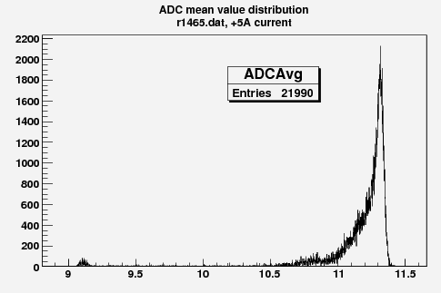
Some examples of ADC mean value distribution. Here are:
1. x axis: ADC mean value for one pulse
2. y axis: number of pulse w/ that ADC mean value
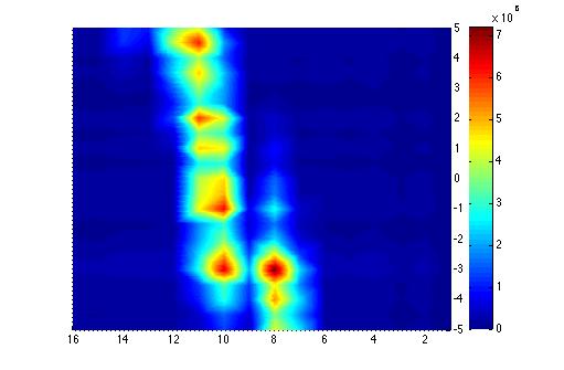
3D Faraday cup plot
Below is the plot of the charge in Faraday cup (pC) as a function of magnet current (vertical axis, A) (basically magnetic field) and ADC (horizontal axis).
