Difference between revisions of "HRRLrun 3-22-26-2010"
| (14 intermediate revisions by the same user not shown) | |||
| Line 127: | Line 127: | ||
No VFAT Runs With triple coincidence, were settings thresholds and other parameters on VFATs. | No VFAT Runs With triple coincidence, were settings thresholds and other parameters on VFATs. | ||
| + | |||
| + | ==Experimental Setup== | ||
==RearPMT+FrontPMT+RF+Rear DC + GEM== | ==RearPMT+FrontPMT+RF+Rear DC + GEM== | ||
| + | |||
| + | The data below have the fron and rear PMTs in coincidence with the accelerator RF as well as the rear Drift chamber and the Qweak GEm detector trigout pulse. | ||
| + | |||
*Run Numbers | *Run Numbers | ||
| Line 207: | Line 212: | ||
GUI representing hits in vfats: [[File:VfatHitsHistogram.png|200px]] | GUI representing hits in vfats: [[File:VfatHitsHistogram.png|200px]] | ||
| + | |||
| + | |||
| + | =Run 1513= | ||
| + | |||
| + | This data has the front and rear PMTs in coincidence with the accelerator RF. | ||
| + | |||
| + | as well as the rear Drift chamber and the Qweak GEm detector trigout pulse. | ||
| + | |||
| + | |||
| + | *TDC Channels | ||
| + | |||
| + | {| border="1" |cellpadding="20" cellspacing="0 | ||
| + | |- | ||
| + | | Detector type || TDC Channel | ||
| + | |- | ||
| + | |Front DC || 4 | ||
| + | |- | ||
| + | |Rear DC || 5 | ||
| + | |- | ||
| + | | Front PMT || 7 | ||
| + | |- | ||
| + | | Rear PMT || 8 | ||
| + | |- | ||
| + | | Qweak GEM || 9 | ||
| + | |} | ||
| + | |||
| + | ==RAW TDC histograms== | ||
| + | |||
| + | TDC conversion | ||
| + | : <math>\frac{1000 {\rm ns}}{2^{12}{\rm chan}}=\frac{1000 {\rm ns}}{4096{\rm chan}}</math> | ||
| + | |||
| + | |||
| + | [[File:Front_PMT_r1413_TDC.png]] | ||
| + | [[File:Front_DC_r1413_TDC.png]] | ||
| + | [[File:GEM_r1413_TDC.png]] | ||
| + | [[File:Rear_DC_r1413_TDC.png]] | ||
| + | [[File:Rear_PMT_r1413_TDC.png]] | ||
| + | |||
| + | == TDC Cuts== | ||
| + | ===Time Diff=== | ||
| + | The time difference between detectors upstream and downstream should be positive. | ||
| + | [[File:Rear-Front_PMT_r1413_TDC.png]] | ||
| + | |||
| + | |||
| + | [[File:Rear-Front_PMT_r1413_TDC_Cut1.png]] | ||
| + | |||
| + | |||
| + | [[File:Rear-Front_DC_r1413_TDC_Cut1.png]] | ||
| + | |||
| + | |||
| + | [[File:Rear-Front_DC_r1413_TDC_CUT1Cut2.png]] | ||
| + | |||
| + | [[File:GEM_r1413_TDC_CUT1Cut2.png]] | ||
| + | |||
| + | |||
| + | ===Time Diff + Non Zero TDC === | ||
| + | |||
| + | It seems that | ||
| + | |||
| + | TDC7 (FrontPMT) >0 (This cut takes out 90% of the data) | ||
| + | |||
| + | The front scintillator must not have been in the trigger for Run 1513? | ||
| + | |||
| + | TDC8-TDC7 >0 | ||
| + | TDC5-TDC4 > 0 | ||
Latest revision as of 15:05, 6 April 2010
HRRL run on March 22-26 2010
Preliminary setup
3/17/10
Install detector infrastructure to mount 2 Drift chambers, 2 Scintillators and 1 GEM on a translator table.
Install collimation
3/18/10
Install all detectors and associated electronics (power supplies, cabling, gas lines,...)
Timing concept
There are 3 modules to be readout; an ADC, a TDC, and the V1495.
The ADC requires a gate defining the integration interval of the pulse. The TDC requires a start pulse to begin the TDC clock and a stop pulse to stop the TDC clock. The V1495 requires a trigger pulse to tell it there is data coming from the VFATs.
The ADC and TDC will be run so they get pulses every time there is a RF pulse. The data are only recorded though if there is a coincidence pulse telling them to keep the data. Otherewise the ADC and TDC will throw the data away.
ADC timing pulse
The linear output of the 3 Fold coincidence module is generated whenever there is an RF pulse from the accelerator and is sent to the 2-channel dual timer. The top channel of the dual timer receives the 3-FOld coincidence linear output and its delayed output is send to the bottom channel of the Dual timer. The bottom of the Dual timer will be used to set the gate width. So use the top channel to adjust the gate such that it is in time with the FC output pulse. Then adjust the bottom channel so the with of the gate integrate over the desired part of the FC output.
TDC timing
3/19/10
install DAQ system and associated readout electronics.
Check channels in histograms
Coincidence: Coincidence between Accelerator's RF pulse generator, and several PMTs
TDC start: Accelerator RF pulse generator. TDC stop: 2 DC, 1 GEM trigout, 4 PMTs
ADC: all FC channels from Accelerator ribbon cable. ADC gate: Create timing gate using scope when accelerator
V1495: Trigger pulse from coincidence logic above
3/22/10
Final day for completing system checks
3/23/10
1pm - 5pm: Tune beam for low and high current
Set the DAQ electronics so the ADC is cleared via the FAST CLEAR input unless there is a coincidence trigger. Set the timing for the ADC gate so it integrates over the FC pulse.
3/24/10
FC
The FC was readout using CODA and the CAEN ADC 792. There were 3 hot channels represent 3 out of the 16 2" bricks stacked up at the end of the accelerator.
Detector tracking run plan
1.) Set the TDC to clear unless there is a coincidence.
The FAST CLEAR on the CAEN 775 TDC did not work like the Fast CLEAR on the CAEN 792. Instead we decided to reset the TDC unless a coincidence pulse is generated which will veto the ADC FAST clear and the TDC reset pulses so they don't happen.
3/25/10
Detector tracking run plan
The VFAT cables delay the GEM trigout pulse by about 229 ns:
Cable delay time is 100 ft + 6 ft + 5 ft = 111 ft (30.96 cm/ft) (1 ns/15 cm) = 229nsec
The VFATs have a latency switch which goes back in time by MCLK cycles.
The MCLK is set to 40 MHz so the latency interval is
Latency = 1/MCLK = 1/40 MHz = 25 ns
229ns/25ns = 9.2 = latency value for VFAT to time in signal from the HRRL cell to the HRRL counting room
We should be able to get the VFAT measurement in time by setting the latency to 9 clock pulses.
First though, set the latency to 0 and set the VFAT threshold so you don;t see any hits.
Then, study how the hits in the VFAT change with latency by changing the latency between values of 8-16.
end the day with everything in time
3/26/10
Work on collimation to optimize detector coincidence and rate. We want a coincidence in all 5 detectors with no pileup.
This means collimation and reduced current.
Once set up we should just take data all day to practice tracking.
All coincidence with RF pulse
First take a data sample with coincidence on front and rear PMTs (2 hours).
Then add the Rear Drift chamber (2 hours)
and then finally see if the GEM trigout can be added and finish running with this configuration.
3/26/10
8:30 am - beam on.
Beam Parameters: Energy - 8.66 MeV, Current - 6 mAmps.
No VFAT Runs With triple coincidence, were settings thresholds and other parameters on VFATs.
Experimental Setup
RearPMT+FrontPMT+RF+Rear DC + GEM
The data below have the fron and rear PMTs in coincidence with the accelerator RF as well as the rear Drift chamber and the Qweak GEm detector trigout pulse.
- Run Numbers
run number is r1513.dat && r1514.dat
- Beam Parameters
| Beam Current (mA) | Beam Energy (MeV) | Rep Rate (Hz) | Event Rate in Coincidence logic (Events/sec) |
| 17 | 14 | 900 | ~1.8 |
- TDC Channels
| Detector type | TDC Channel |
| Front DC | 4 |
| Rear DC | 5 |
| Front PMT | 7 |
| Rear PMT | 8 |
| Qweak GEM | 9 |
- VFAT Settings
Latency for all cards 0x12
MSPolarity = On
These threshold values were set by turning the GEM detector voltage off and setting the threshold right above where we were getting any hits. During the run we turned the GEM detector voltage up to 3600 V.
VThreshold1 16 = 0x98
VThreshold1 48 = 0x98
VThreshold1 64 = 0x9c
VThreshold1 80 = 0x98
VThreshold1 96 = 0x9E
VThreshold1 112 = 0xA4
MSPulseLength<2:0> = 0x7
- HV Settings on Detectors:
| Detector type | HV Settings (Volts) |
| PMTs(Front && Rear) | -1104 |
| DCs (Metalica && Plastika) | S:F:G=1400:-700:980) |
| Qweak GEM | Drift:GEM=-3600/3300 |
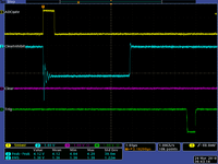
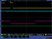
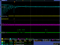
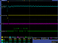
- Scope Pictures
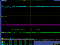
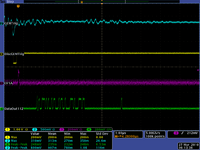
Below is shown the scope picture of the TDC start and stop, as a stop i have Qweak GEM discriminated trigout pulse:
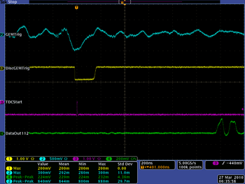
GUI representing hits in vfats: 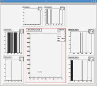
Run 1513
This data has the front and rear PMTs in coincidence with the accelerator RF.
as well as the rear Drift chamber and the Qweak GEm detector trigout pulse.
- TDC Channels
| Detector type | TDC Channel |
| Front DC | 4 |
| Rear DC | 5 |
| Front PMT | 7 |
| Rear PMT | 8 |
| Qweak GEM | 9 |
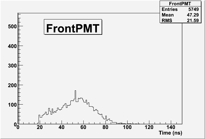
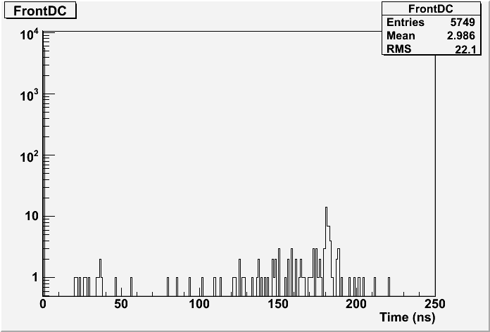
RAW TDC histograms
TDC conversion
TDC Cuts
Time Diff
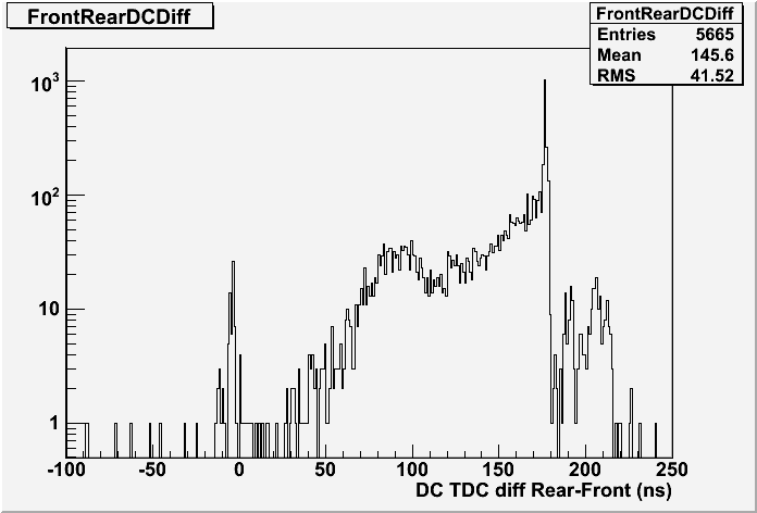
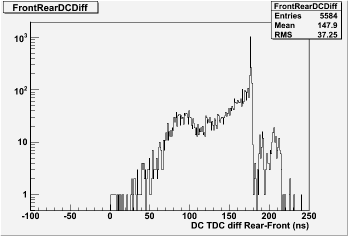
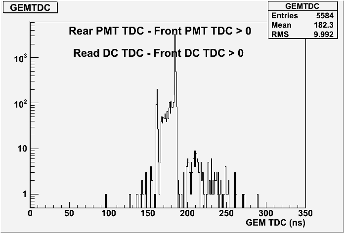
The time difference between detectors upstream and downstream should be positive.
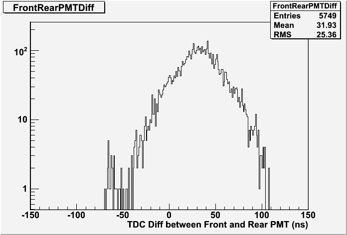
File:Rear-Front PMT r1413 TDC Cut1.png
Time Diff + Non Zero TDC
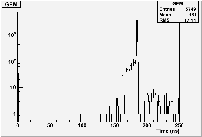
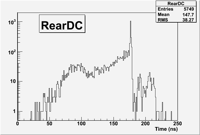
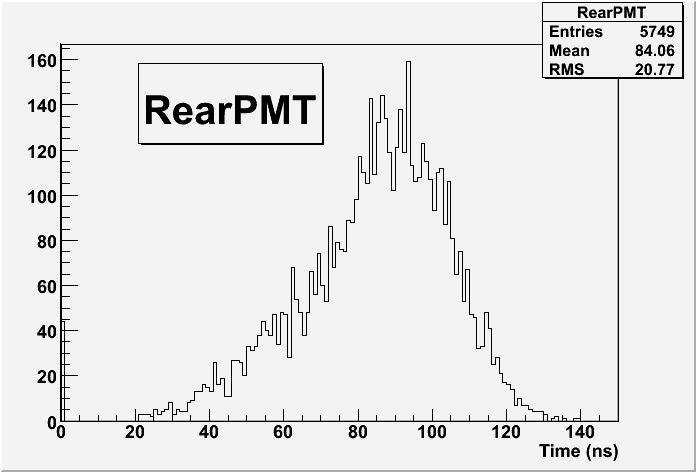
It seems that
TDC7 (FrontPMT) >0 (This cut takes out 90% of the data)
The front scintillator must not have been in the trigger for Run 1513?
TDC8-TDC7 >0 TDC5-TDC4 > 0
