Difference between revisions of "GEM Cosmic V792 Measurements"
| Line 119: | Line 119: | ||
=12-13-08= | =12-13-08= | ||
| − | |||
| − | |||
| − | |||
| − | |||
| − | |||
| − | |||
| − | |||
| − | |||
| − | |||
| − | |||
| − | |||
| − | |||
| − | |||
| − | |||
| − | |||
==GEM Data== | ==GEM Data== | ||
Revision as of 23:06, 17 December 2008
DAQ setup
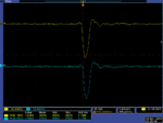
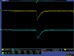
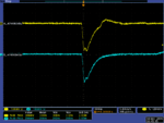
A Stanford Pulse Generator, Model DG535, was used to create signals similar to the GEM output pulse. Two identical signals (A && B) were injected into the Timing Filter Amplifiers to set the amplifier gain of each channel to the same value. Pulse A was injected to the Timing Filter Amplifier, Model 474-09 and Signal B was going into the Model 474-09. Integration time was set to 20 ns on each Timing Filter Amplifier. Coarse gain and Fine gain were set so that the Amplification for each channel was the same.
After matching the amplifier gain, the output pulse A from the Timing Filter Amplifier, Model 474-09, was tee'd. One output was amplified again, using Timing Filter Amplifier and the second output was delayed and putted into the ADC with delayed and amplified B pulse.
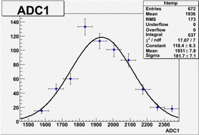
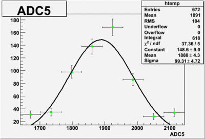
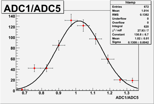
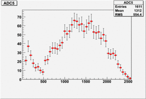
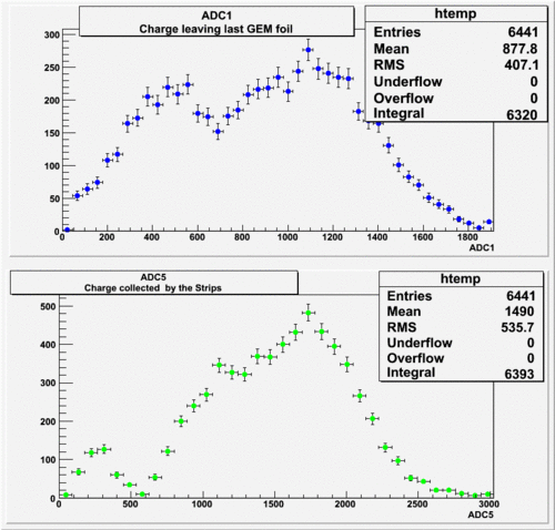
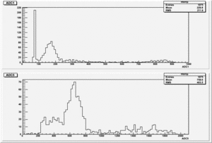
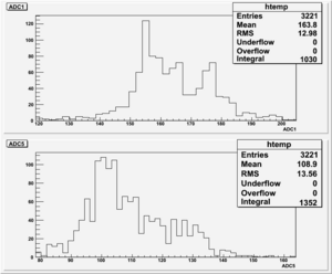
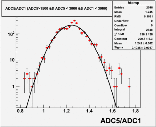
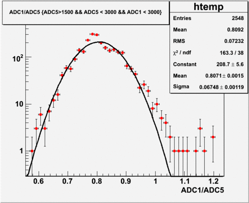
First two histograms below show the ADC results for two amplified pulses, and the last histogram shows the ratio of ADC1/ADC5. As one can notice, the charge ratio is close to one, mean value is ~ 1.
- Run Number 650.dat
GEM Measurements
12-10-08
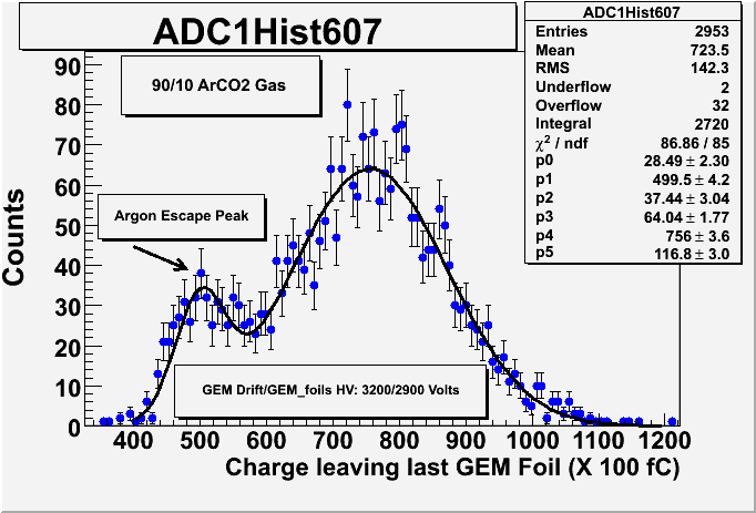
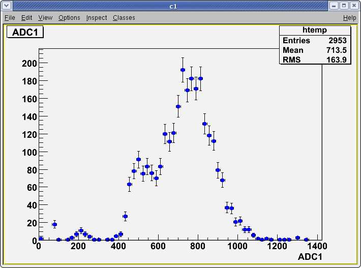
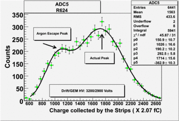
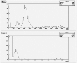
The signal below represents a measurement of the Trig out signal from a 10 cm x 10 cm ionization chamber with 3 GEM preamplifiers. The chamber gas a 90/10 % mixture of Arcon and CO2. The Drift HV was set to 3200 Volts and the GEM preamplifier HV distribution network was set to 2900 Volts. The V792 CAEN ADC channels have a gain of 100 fC/channel. The main signal peak appears at channel number 759 and represents an accumulation of pC of charge.
Electronics Settings:
TrigOut goes to Timing Filter Amplifier(Coarse Gain=X6, Fine GAin=7.5ns && Integrate=20ns) and after amplification to ADC
StripOut is used as a trigger and gate. The signal from the strip is amplified by the Timing Filter Amplifier (Coarse Gain=X20, Fine Gain=12.5ns && Integrate=500ns)
The Threshold on DIFF. CFD is set to 0.70 (ULD=9.9~10 && LLD=0.5)
12-10(11)-08
HV Settings: Volts and Volts.
Using again only TrigOut and the signal from the Strip.
Electronics Setup: done (might change CFD threshold)
12-11-08
HV Settings: Volts and Volts.
Gas type 90/10 ArCO2.
Electronics Setup
TrigOut and the stripsignal, both are used as a pulse and go to ADC.
The pulse from the Strips is used as a trigger and gate.
The pulse from the trigout is delayed, Amplified by the Timinig Filter Amplifier(Coarse_Gain=X20, Fine_Gain=8.5 && Integrate=20ns).
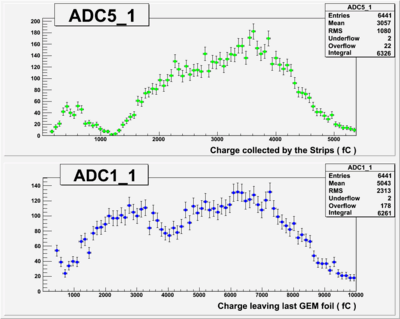
Signal from the Strips goes to the Timing Filter Amplifier(Coarse_Gain=X20, Fine_Gain=10.5 && Integrate=20ns). Amplified pulse is devided into two signals, One is sued as a trigger and gate and second as a pulse for ADC. The first one(gate && trigger) is amplified using the Timing Filter Amplifier(Coarse_Gain=X2, Fine_Gain=10 && Integrate=50ns) and used in DIFF. CFD for gate and trigger. Second output from the Amplified strips, goes to delay box(TENNELEC TC 215 DELAY AMPLIFIER) and putted to the ADC.
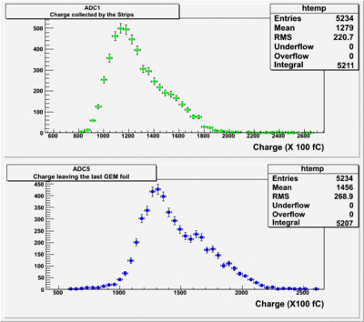
The results shown below are for different Diff. CFD values.
1). Threshold Values: Threshold=1.90, ULD=9.65 && LLD=2.10
Run Number is r613
Start time: Dec 11 16:31:42 End Time: Dec 11 17:32:23
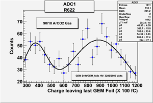
2). Threshold Values: Threshold=3.10, ULD=9.65 && LLD=2.90
Run Number is r622
Start time: Dec 11 19:25:28 End Time: Dec 11 21:53:44
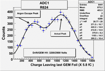
2). Threshold Values: Threshold=3.70, ULD=9.65 && LLD=3.50
Run Number is r624
Start time: Dec 11 21:58:37 End Time: Dec 12 12:19:53
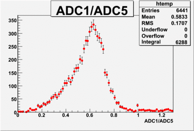
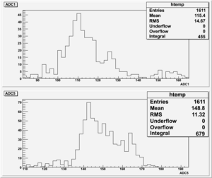
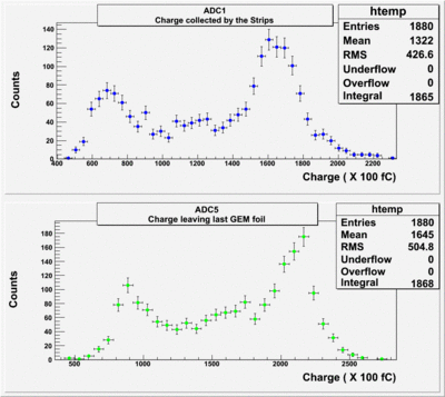
The result shown below is reasonable. The charge that left the last GEM foil is greater than the charge collected by the strips.
12-12-08
Finding out what is gain for each channel using the Stanford pulse generator.
Setting:
Run Number: r634 && r635
Original pulse from stanford pulse generator goes to the ADC: r636 && r637
I used the attenuator for both channels and it was set to the same value: 12dB = 10.7918.
Gain Calculation
Gain_for_Channel_1 = Gain_TrigOut =
Gain_for_Channel_5 = Gain_Strip =
12-13-08
GEM Data
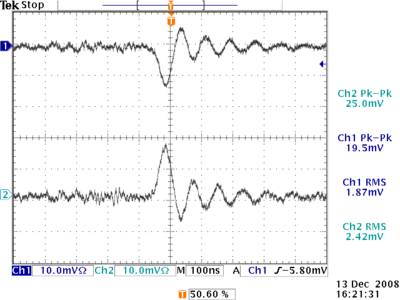
Below Channel 1 represents StripOut and Channel 2 trigOut.
- Run Number r651
Start Time: Dec 13 19:43:14 and End Time: Dec 14 00:21:47
Electronics Settings:
TrigOut.)
Timing Filter Amplifier Model 474-06(Coarse Gain=X10, Fine Gain=5 && Integrate=20ns)
StripOut.)
Timing Filter Amplifier Model 474-09(Coarse Gain=X10, Fine Gain=5 && Integrate=20ns)
Pulse for DIFF. CFD
Timing Filter Amplifier Model 474-02(Coarse Gain=X4, Fine Gain=2 && Integrate=20ns)
DIFF. CFD(Threshold= 3, LLD=2.80 && ULD=9.55)
The Amplification on Strip pulse and TrigOut is the same. Signal is amplified and delayed after amplification.
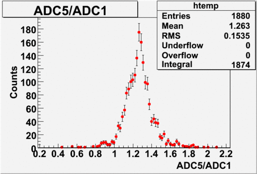
Charge leaving last GEM foil divided by the charge that was collected by the Strips.
- Run Number r653
Electronics Settings are the same, only integration time is set to 50ns for both signals(Strip and TrigOut)
Start Time: Dec 14 00:39:31 and End Time: Dec 14 16:07:21
11-07-08
The pulse coming from the strips is delayed and amplified using the Timing Filter Amplifier Model_474(X6). The amplified pulse is connected to the V792 QDC.
Run 550
Start Time: Nov 6 19:58:03; End Time: Nov 7 09:45:57
