Difference between revisions of "Uranium target test"
Jump to navigation
Jump to search
| Line 7: | Line 7: | ||
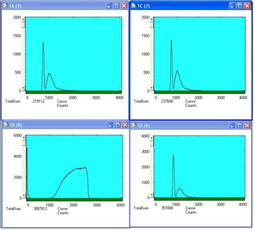
On the picture: 1D - timing spectrum taken by upper detector, 1C - timing spectrum taken by side detector, 1A - timing spectrum taken by side reference (being kept stationary) detector, 1B - NaI accelerator current monitor | On the picture: 1D - timing spectrum taken by upper detector, 1C - timing spectrum taken by side detector, 1A - timing spectrum taken by side reference (being kept stationary) detector, 1B - NaI accelerator current monitor | ||
| − | + | The target is replaced by small cylindrical jar... | |
[http://www.iac.isu.edu/mediawiki/index.php/October_Fission_HRRL_Measurements_2008 Go Back] | [http://www.iac.isu.edu/mediawiki/index.php/October_Fission_HRRL_Measurements_2008 Go Back] | ||
Revision as of 17:25, 20 October 2008
First, a uranium plate is used, dimentions (approximately): 15cm x 12.5 cm x 3.5 mm
On the picture: 1D - timing spectrum taken by upper detector, 1C - timing spectrum taken by side detector, 1A - timing spectrum taken by side reference (being kept stationary) detector, 1B - NaI accelerator current monitor
The target is replaced by small cylindrical jar...
