Difference between revisions of "PFD:Production of Fabrication Drawings"
| (7 intermediate revisions by the same user not shown) | |||
| Line 8: | Line 8: | ||
= Drawings= | = Drawings= | ||
| + | |||
| + | These Drawings are based on the following parameters | ||
| + | |||
| + | 1. 10mm of wire feed through is projected inward from the end plate | ||
| + | |||
| + | 2. The Maximum diameter of the ring which would touch all the nose plate faces is 10 inches | ||
| + | |||
| + | 3. Distance between wire planes in super layer 5 is 8.6 mm | ||
| + | |||
| + | 4. Distance between wire planes in super layer 6 is 9 mm | ||
| + | |||
| + | 5. Chamber tilt angle is 25 Degrees | ||
| + | |||
| + | 6. Min Electron Scattering angle is 4.5 Degrees | ||
| + | |||
| + | 7. Distance to the first sense wire from the target center is 4.804842 meters | ||
| + | |||
| + | 8. Wire angles are 6 degrees with opposite slopes on the center line with reference to a horizontal in the chamber tilt plane | ||
| + | |||
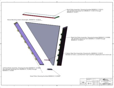
| + | Assembly drawing of a sector [[Image:Sep25. B00000-01-10-0001.pdf]] | ||
| + | |||
| + | [[Image:AssemblyDrawing_9-25-08.jpg | 400 px]] | ||
| + | |||
| + | |||
==Nose Plate== | ==Nose Plate== | ||
[[Image:Sep25. B00000-01-10-0002.pdf]] | [[Image:Sep25. B00000-01-10-0002.pdf]] | ||
| Line 94: | Line 118: | ||
[[Image:Sep. B00000-01-10-00018.pdf]] | [[Image:Sep. B00000-01-10-00018.pdf]] | ||
| − | ==Chamber holding support | + | ==carbon rods== |
| + | |||
| + | [[Image:Sep. B00000-01-10-00019.pdf]] | ||
| + | |||
| + | ==Chamber holding support plates== | ||
[[Image:Sep. B00000-01-10-00020.pdf]] | [[Image:Sep. B00000-01-10-00020.pdf]] | ||
Latest revision as of 14:36, 16 October 2008
Drawings should include the following information
- dimension units (mm or inch)
- Vendor
- tolorances
- assembly drawing number
- material finish when appropriate
Drawings
These Drawings are based on the following parameters
1. 10mm of wire feed through is projected inward from the end plate
2. The Maximum diameter of the ring which would touch all the nose plate faces is 10 inches
3. Distance between wire planes in super layer 5 is 8.6 mm
4. Distance between wire planes in super layer 6 is 9 mm
5. Chamber tilt angle is 25 Degrees
6. Min Electron Scattering angle is 4.5 Degrees
7. Distance to the first sense wire from the target center is 4.804842 meters
8. Wire angles are 6 degrees with opposite slopes on the center line with reference to a horizontal in the chamber tilt plane
Assembly drawing of a sector File:Sep25. B00000-01-10-0001.pdf
Nose Plate
File:Sep25. B00000-01-10-0002.pdf
Left End Plate
Left End Plate assembly was drawn in 5 Drawings to complete the assembly
Left End Plate Assembly View: File:Sep25. B00000-01-10-0003.pdf
- A sample of hole positions are available in sheet 2
Left End Plate Frame: Frame has 5 sheets File:Sep25. B00000-01-10-0004.pdf
- Sheet 1: Frame assembly
- Sheet 2: Upstream Close out
- Sheet 3. Downstream Close out
- Sheet 4. Nose side Close Out
- Sheet 5. back plate side Close Out
Left End Plate Core: Core File:Sep25. B00000-01-10-0005.pdf
Left End Plate inner skin: File:Sep25. B00000-01-10-0006.pdf
Left End Plate outer skin: File:Sep25. B00000-01-10-0007.pdf
Right End Plate
Right End Plate assembly was drawn in 5 Drawings to complete the assembly
Right End Plate Assembly View: File:Sep25. B00000-01-10-0008.pdf
- A sample of hole positions are available in sheet 2
Left End Plate Frame: Frame has 5 sheets File:Sep25. B00000-01-10-0009.pdf
- Sheet 1: Frame assembly
- Sheet 2: Upstream Close out
- Sheet 3. Downstream Close out
- Sheet 4. Nose side Close Out
- Sheet 5. back plate side Close Out
Right End Plate Core: Core File:Sep25. B00000-01-10-0010.pdf
Right End Plate inner skin: File:Sep25. B00000-01-10-0011.pdf
Right End Plate outer skin: File:Sep25. B00000-01-10-0012.pdf
Back Plate
Back Plate assembly was drawn in 5 Drawings to complete the back plate assembly
Back Plate Assembly View: File:Sep. B00000-01-10-00013.pdf
Back Plate Frame: Frame has 5 sheets File:Sep. B00000-01-10-00014.pdf
- Sheet 1: Frame assembly
- Sheet 2: Upstream Close out
- Sheet 3. Downstream Close out
- Sheet 4. Right Close Out
- Sheet 5. left Close Out
Back Plate Core: File:Sep. B00000-01-10-00015.pdf
Back Plate inner skin: File:Sep. B00000-01-10-00016.pdf
Back Plate outer skin: File:Sep. B00000-01-10-00017.pdf
Hexcel Backing sheet
File:Sep. B00000-01-10-00018.pdf
carbon rods
File:Sep. B00000-01-10-00019.pdf
