Difference between revisions of "VFAT readout electronics"
Jump to navigation
Jump to search
| Line 5: | Line 5: | ||
== VFAT Board specifications== | == VFAT Board specifications== | ||
== signals== | == signals== | ||
| − | ===[[LVDS]] | + | ===LVDA signals ===[[LVDS]]<br/> |
| − | ===[[I2C]] | + | ===I2C signals===[[I2C]]<br/> |
== Breakout box specs (preliminary) == | == Breakout box specs (preliminary) == | ||
Revision as of 20:50, 17 July 2007
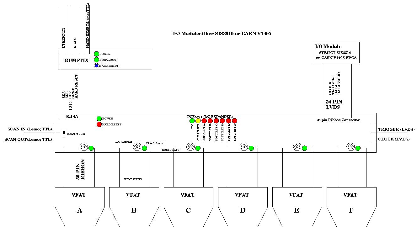
VFAT readout Block Diagram
A VFAT board from CERN is evaluated for use as a readout board to convert the GEM output analog signal to a digital signal.
VFAT Board specifications
signals
===LVDA signals ===LVDS
===I2C signals===I2C
Breakout box specs (preliminary)
- 6 inputs for ~1m ribbon cables from VFAT modules
- 3-bit DIP switch to select I2C address range for each VFAT
- Soft reset for each VFAT controlled via I2C expander chip
- Shared hard reset line from Gumstix
- Scan Mode switch
- ScanIn connector (cascaded)
- ScanOut connector (cascaded)
- RJ45 port to gumstix box containing I2C and other signals:
- Power (3.3 or 2.5V)
- Ground
- SDA
- SCL
- Hard Reset
- Extra line for Link detection
- 34 pin ribbon connector for LVDS signals
- LEMO connector for LVDS trigger input
- LEMO connector for LVDS Master Clock
- I2C expander(s) for status LEDs (socketed)
- Status LEDs:
- Power (from I2C line)
- I2C connect (flashing through I2C expand)
- Power for each VFAT (feedback through common pins on VFAT board?)
- Hard Reset LED
- Clear UpsetReg (SEU counter) via I2C expand
Ribbon cable pinouts
| # | Name | Value | Test rig color Primary/Second |
| B1 | DGND | Digital Ground | Black/Grey (shared) |
| A1 | DVDD | +2.5V | Red/Grey (shared) |
| B2 | SDA | I2C Data | Green/Yellow |
| A2 | SCL | I2C Clock | Yellow/Green |
| B3 | DGND | Digital Ground | Black/Grey (shared) |
| A3 | DVDD | +2.5V | Red/Grey (shared) |
| B4 | |||
| A4 | |||
| B5 | I2C ADDR 2 | I2C Address Most | White/Blue |
| A5 | I2C ADDR 1 | I2C Address Middle | White/Orange |
| B6 | I2C ADDR 0 | I2C Address Least | White/Green |
| A6 | REH-S | Soft Reset (Program saved) | White/Grey |
| B7 | |||
| A7 | REH-B | Hard Reset | Grey/White |
| .............. | |||
|---|---|---|---|
| B22 | DGND | Digital Ground?? | |
| A22 | SCAN E | ||
| B23 | AGND | Analog Ground | |
| A23 | AVDD | 2.5V | Grey/Red |
| B24 | AGND | Analog Ground | |
| A24 | AVDD | 2.5V | Grey/Red |
| B25 | AGNDD | Analog Ground?? | Grey/Black |
| A25 | AVDD | 2.5V | Grey/Red |
The PC board-mount socket for the cable is ERNI 154765 for reel or ERNI 063197 for tube packaging.
The cable crimp-ons are ERNI 024403 or premade cables 300mm long are ERNI 173795
