Difference between revisions of "DDP:Detailed Design Phase: Drawing and Assembly Package"
| Line 140: | Line 140: | ||
[[Image:assembly20_jun_13.png| 400 px]] | [[Image:assembly20_jun_13.png| 400 px]] | ||
| − | A detailed drawing of back plate Core can be viewed at [[Image: | + | A detailed drawing of back plate Core can be viewed at [[Image:B00000-01-10-0008.pdf]] |
| − | A detailed drawing of back plate skin can be viewed at [[Image: | + | A detailed drawing of back plate skin can be viewed at [[Image:B00000-01-10-0009.pdf]] |
| − | A detailed drawing of back plate casing can be viewed at [[Image: | + | A detailed drawing of back plate casing can be viewed at [[Image:B00000-01-10-0010.pdf]] |
===Backing Sheet=== | ===Backing Sheet=== | ||
Revision as of 22:53, 26 June 2008
Detailed Design Drawing Report 6/27/08
Outline:
1.) Dimensions
2.) Constraints: Case 3 from progress report: constrain triangle and nose plate on upstream side.
3.) Deflection Analysis
Steps:
a.) check triangle contact region and its mass b.) add another carbon fiber rod c.) increase size of back plate
4.) Drawings
drawings in PDF format
a.) Endplate structural drawing (no holes just shaded area)
b.) Drawings for all other parts
c.)
d.) Copy old R3 (take advantage of no curved window.
Report
Introduction
Initial parameters to be followed to fulfill to satisfy design Criteria
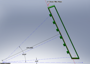
1. Distance from target to first sense wire plane along a ray which is normal to the end plate = 4746.5 mm
2. Chamber Tilt Angle = 25 Degrees
3. Maximum Scattering Angle = 45.05 Degrees
4. Minimum Scattering Angle = 4.5 Degrees
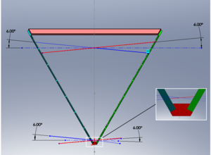
5. Wires are at 6 Degrees to the horizontal in each of its wire planes
Assembly
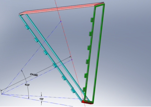
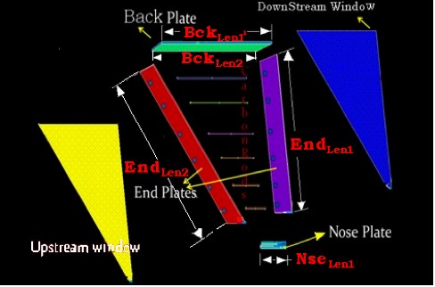
The Assembly of each sector in the region 3 drift chamber can be considered similar to each other. Each assembly can be divided into sub-assemblies like
1. Nose Plate
2. Right End Plate
3. Left End plate
4. Back plate
5. Backing Sheet
6. Carbon rods
7. Attachments: These are the external geometric parts of each sector, used for clamping and mounting each sector. so, they might change with the orientation of each sector
A detailed drawing of this Basic sector assmebly can be viewed at File:B00000-01-10-0001.pdf
Nose Plate
Nose plate is the plate where both the end plates are attached to it on either side
A detailed drawing of Nose plate can be viewed at File:B00000-01-10-0002.pdf
Right end plate
Left end plate is the end plate to the left hand side if we are viewing from the target.
They can be referenced with left and right to show each sub assembly.
A detailed drawing of right end plate Core can be viewed at File:B00000-01-10-0003.pdf
A detailed drawing of right end plate skin can be viewed at File:B00000-01-10-0004.pdf
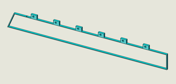
Since end plate casing will not have holes for wires, the drawing for left end plate casing and right end plate casing will be the same.
A detailed drawing of End plate casing can be viewed at File:B00000-01-10-0005.pdf
Left End Plate
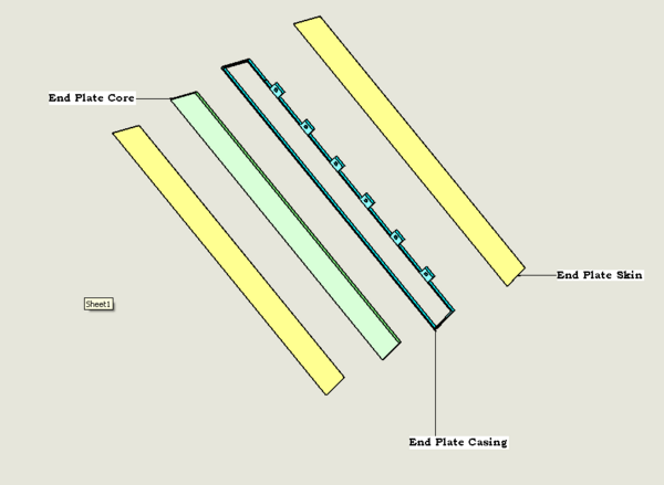
Left end plate is the end plate to the left hand side if we are viewing from the target. Left end plate and the right end plate are same with parts and its dimensions. However, the hole locations differ between each other.
Each end plate sub assembly consists of 3 parts, namely
End plate casing - Made of Aluminum.
They can be referenced with left and right to show each sub assembly.
A detailed drawing of Left end plate Core can be viewed at File:B00000-01-10-0006.pdf
A detailed drawing of Left end plate skin can be viewed at File:B00000-01-10-0007.pdf
Back Plate
Back plate is the plate which connects the left end plate and right end plate on the top.
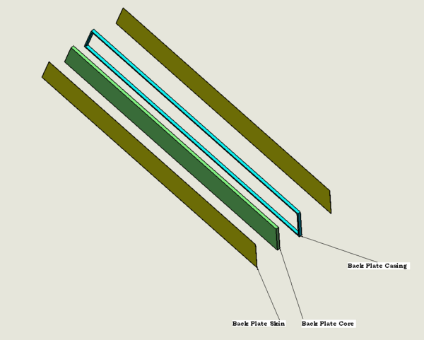
Back plate sub assembly consists of 3 parts, namely
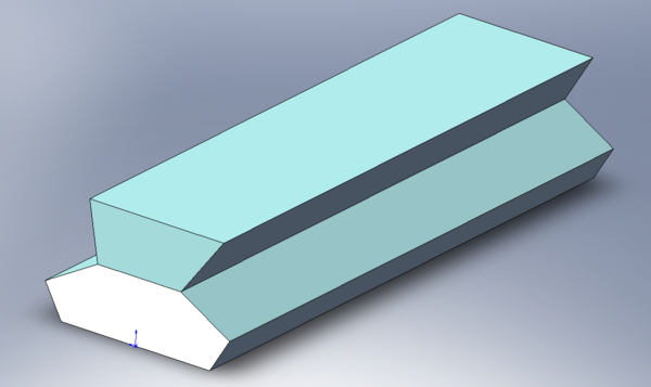
Back plate Core - made of Polyurethane
Back plate Skins - 2 No's- Made of stainless steel
Back plate casing - Made of Aluminum
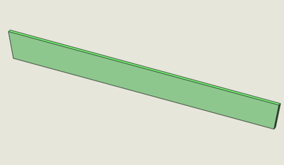
A detailed drawing of back plate Core can be viewed at File:B00000-01-10-0008.pdf
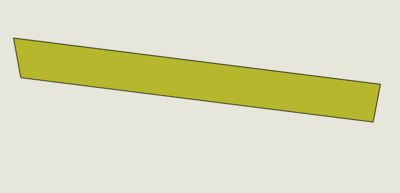
A detailed drawing of back plate skin can be viewed at File:B00000-01-10-0009.pdf
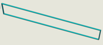
A detailed drawing of back plate casing can be viewed at File:B00000-01-10-0010.pdf
Backing Sheet
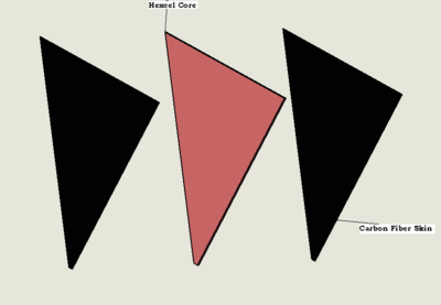
Backing sheet is the large sheet which is mounted on the downstream side of sector.
It consists of 2 parts, namely
Hexcel Core and Carbon fiber skins on either side
A detailed drawing of back plate Core can be viewed at File:Assembly20 jun 14.pdf
A detailed drawing of back plate skin can be viewed at File:Assembly20 jun 15.pdf
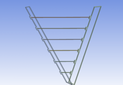
Carbon fiber rods
These rods are mounted on the upstream side of each sector, connecting the left end plate aluminum casing and right end plate aluminum casing..
There are 6 Carbon rods each of outer diameter of 50.8 mm and inner diameter of 48.26mm
A detailed drawing of carbon fiber rods can be viewed at File:Assembly20 jun 16.pdf
