Difference between revisions of "CHIPS IAC Run 5-27-08"
Jump to navigation
Jump to search
| (13 intermediate revisions by the same user not shown) | |||
| Line 14: | Line 14: | ||
[[Image:CHIPS_IAC_5-27-08_90DegreePort_MinSpotSize.jpg | 200 px]] | [[Image:CHIPS_IAC_5-27-08_90DegreePort_MinSpotSize.jpg | 200 px]] | ||
[[Image:CHIPS_IAC_5-27-08_90DegreePort_MinSpotSize_20MicroAmps.jpg | 200 px]] | [[Image:CHIPS_IAC_5-27-08_90DegreePort_MinSpotSize_20MicroAmps.jpg | 200 px]] | ||
| + | |||
| + | |||
| + | {| border="1" |cellpadding="20" cellspacing="0 | ||
| + | |- | ||
| + | |Device || setting | ||
| + | |- | ||
| + | | RS1 || 0+ | ||
| + | |- | ||
| + | | RS2 || 0- | ||
| + | |- | ||
| + | |FS1 || 0+ | ||
| + | |- | ||
| + | |FS2 || 0- | ||
| + | |- | ||
| + | |0Q1 || -2.62 | ||
| + | |- | ||
| + | |0Q2 || +4.04 | ||
| + | |- | ||
| + | |45Q1 || -1.88 | ||
| + | |- | ||
| + | |45Q2 || +1.74 | ||
| + | |- | ||
| + | |L90Q1 || -0 | ||
| + | |- | ||
| + | |L90Q2 || +2.87 | ||
| + | |- | ||
| + | |Bend1 || 3.5 | ||
| + | |- | ||
| + | |Bend2 || 0.86 | ||
| + | |- | ||
| + | |Gun HV|| 3 kV | ||
| + | |- | ||
| + | |Grid|| 0.43 | ||
| + | |- | ||
| + | |802 || 16 kV | ||
| + | |} | ||
=Max Transmission= | =Max Transmission= | ||
| Line 19: | Line 55: | ||
Retune machine to maximize transmission between the FC collar and the FC. | Retune machine to maximize transmission between the FC collar and the FC. | ||
| − | [[Image:CHIPS_IAC_5-27-08_ZeroDegreePort_MaxTransmission.jpg]] | + | [[Image:CHIPS_IAC_5-27-08_ZeroDegreePort_MaxTransmission.jpg | 200 px]][[Image:CHIPS_IAC_5-27-08_90DegreePort_MaxTransmission.jpg | 200 px]] |
| + | |||
| + | Using FrameGrabber | ||
| + | |||
| + | [[Image:CHIPS_IAC_5-27-08_0DegreePort_MaxTransmission_FrameGrabber.jpg | 200 px]] | ||
| + | [[Image:CHIPS_IAC_5-27-08_90DegreePort_MaxTransmission_FrameGrabber.jpg | 200 px]] | ||
| + | |||
| + | [[Image:CHIPS_IAC_5-27-08_FC-CollarRatio.jpg | 200 px]] | ||
| + | |||
| + | |||
| + | {| border="1" |cellpadding="20" cellspacing="0 | ||
| + | |- | ||
| + | |Device || setting | ||
| + | |- | ||
| + | | RS1 || 0+ | ||
| + | |- | ||
| + | | RS2 || 0- | ||
| + | |- | ||
| + | |FS1 || 0+ | ||
| + | |- | ||
| + | |FS2 || 0- | ||
| + | |- | ||
| + | |0Q1 || -0.20 | ||
| + | |- | ||
| + | |0Q2 || +2.86 | ||
| + | |- | ||
| + | |45Q1 || -0.004 | ||
| + | |- | ||
| + | |45Q2 || +2.24 | ||
| + | |- | ||
| + | |L90Q1 || -1.33 | ||
| + | |- | ||
| + | |L90Q2 || +2.42 | ||
| + | |- | ||
| + | |Bend1 || 3.5 | ||
| + | |- | ||
| + | |Bend2 || 0.86 | ||
| + | |- | ||
| + | |Gun HV|| 13 kV | ||
| + | |- | ||
| + | |Grid|| 2.31 | ||
| + | |- | ||
| + | |802 || 16 kV | ||
| + | |- | ||
| + | |SOL1 || 0.39 | ||
| + | |- | ||
| + | |SOL2 || 0.40 | ||
| + | |} | ||
| − | |||
| − | [ | + | [http://www.iac.isu.edu/mediawiki/index.php/CHIPS_Run_May-2008 Go Back] |
Latest revision as of 11:12, 28 May 2008
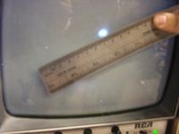
Beam Tuning pictures:
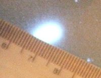
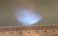
Smallest beam spot at 0 Degree port
The beam appears to light up a 3 mm diameter circle on the Phosphorus screen.
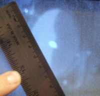
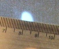
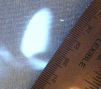
Smallest beam spot at 90 Degree port
The beam appears to light up a diameter circle on the Phosphorus screen with of beam current.
| Device | setting |
| RS1 | 0+ |
| RS2 | 0- |
| FS1 | 0+ |
| FS2 | 0- |
| 0Q1 | -2.62 |
| 0Q2 | +4.04 |
| 45Q1 | -1.88 |
| 45Q2 | +1.74 |
| L90Q1 | -0 |
| L90Q2 | +2.87 |
| Bend1 | 3.5 |
| Bend2 | 0.86 |
| Gun HV | 3 kV |
| Grid | 0.43 |
| 802 | 16 kV |
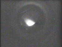
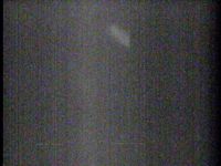
Max Transmission
Retune machine to maximize transmission between the FC collar and the FC.
Using FrameGrabber
| Device | setting |
| RS1 | 0+ |
| RS2 | 0- |
| FS1 | 0+ |
| FS2 | 0- |
| 0Q1 | -0.20 |
| 0Q2 | +2.86 |
| 45Q1 | -0.004 |
| 45Q2 | +2.24 |
| L90Q1 | -1.33 |
| L90Q2 | +2.42 |
| Bend1 | 3.5 |
| Bend2 | 0.86 |
| Gun HV | 13 kV |
| Grid | 2.31 |
| 802 | 16 kV |
| SOL1 | 0.39 |
| SOL2 | 0.40 |
