Difference between revisions of "CAEN V775 TDC"
| Line 103: | Line 103: | ||
C = T+ 100 ns | C = T+ 100 ns | ||
| − | D = T + | + | D = T + 140 ns |
For Channel 0 I injected the pulses | For Channel 0 I injected the pulses | ||
Revision as of 00:29, 29 November 2008
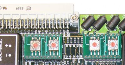
| Address | |
| Pin | Setting |
| SW 1 | 1 |
| SW 2 | 6 |
| SW 3 | 0 |
| SW 4 | 8 |
initialize TDC
-> c775Init(0x610000)
Initialized TDC ID 0 at address 0x90610000
Common Start/Stop =
BitSet 2 is used to set the TDC in common start or stop mode.
0 => common start
1 => common start
Use the Status function to see what the bit is set at
-> c775Status(0)
STATUS for TDC id 0 at base address 0x90610000
----------------------------------------------
Interrupts Disabled
Last Interrupt Count    : 0
            --1--  --2--
 Status  = 0x0050 0x0002
 BitSet  = 0x0000 0x0898
 Control = 0x0000
 FSR     = 140 nsec
 Event Count     = (No Events Taken)
 Last Event Read = (No Events Read)
value = 37 = 0x25 = '%'
BitSet 2 is set to 0x0898 = 100010011000 d
The above has bit 10 ( starting from 0 at the very left) set to 0 => common start
Read Data
Use PrintEvent to print out the data in the TDC to the ROC console
-> c775PrintEvent
 TDC DATA for Module 0
 Header: 0xfa000100   nWords = 1
     0xf80048b8
 Trailer: 0xfc00005a   Event Count = 90
value = 3 = 0x3
Decoding the data
Header
Header = 0xfa000100 = 11111010000000000000000100000000 b
bits 27-31 contain the GEO address = 11111 d = 0xF bits 26-24 contain the type of word 010 => header bits 16-23 contain the crate number = 00000000 => crate 0 bits 8-13 contain the number of channels contained in the data word = 000001 = 1 TDC channel
Data Words
data = 0xf80048b8 = 11111000000000000100100010111000 b
bits 27-31 contain the GEO address = 11111 d = 0xF bits 26-24 contain the type of word 000 => dataum bits 16-20 contain the channel number = 00000 => channel 0 bit 14 = data valid bit = 1 => valid data bit 13 = underthreshold bit bit 12 = overflow bit 0 => ADC not in overflow bits 0-11 contain the TDC value = 100010111000 b = 0x8b8 = 2232 d
The TDC value for channel 0 is 2232 channels.
The manuals says the TDC has a rang from 140 ns to 1.2 \mu s with 8 bit resolution
I used the Stanfor pulse generator to generate 2 NIM pulses and then sent those to a NIM to ECL converter in order to create 2 ECL pulses which the TDC accepts as input.
I set the delays to
A = T+0
B = T+ 60 ns
C = T+ 100 ns
D = T + 140 ns
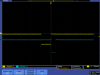
For Channel 0 I injected the pulses
The distance between the falling part of each pulse is about 200 ns
A = T+0
B = T+ 60 ns
C = T+ 100 ns
D = T + 280 ns
-> c775PrintEvent
 TDC DATA for Module 0
 Header: 0xfa000100   nWords = 1
     0xf80048b1
 Trailer: 0xfc00005b   Event Count = 91
value = 3 = 0x3
Data = 0xf80048b1 = 11111000000000000100100010110001 b
bits 0-11 = 100010110001 b = 2225 d = 0x 8b1

