Difference between revisions of "He3Tube Equipment"
| (128 intermediate revisions by 3 users not shown) | |||
| Line 1: | Line 1: | ||
| − | He3 Tube neutron detectors, 1200 Volts with EG&G (ortec) pre amp Model 142PC (Serial #787) | + | [[2nCor_44#Equipment]] |
| + | |||
| + | =Analog Signals= | ||
| + | |||
| + | He3 Tube neutron detectors are 52 cm long and 1.5 cm radius cylinders, 1200 Volts with EG&G (ortec) pre amp Model 142PC (Serial #787) | ||
| + | |||
| + | Although 1200 Volts is applied to the Ortec Preamp, only 350 Volts is established on the "input" port where the Tube is plugged in. If 1250 Volts is applied, then 366 Volts is observed. | ||
[[File:He3Signal_NoSource_4-2017.png | 300 px]] | [[File:He3Signal_NoSource_4-2017.png | 300 px]] | ||
| + | |||
| + | For the TENNELEC you need to apply 1650 Volts to get 362 applied to the Tube | ||
| + | |||
| + | |||
| + | The TENNELEC signal output at 1550 Volts has less noise with signal at about 30 mV compared to the output of the ortec. There is a230 mV DC offset on the output | ||
| + | [[File:He3Signal_NoSource_4-6-2017.png | 300 px]] | ||
| + | |||
| + | =Output measured by CAEN V785N Peaks sensing ADC= | ||
| + | |||
| + | Using a Cf-252 source positions on a shelf below the He-3 tube covered by 2" thick virgin Poly and set to 1250 Volts. Using Ortec pre-amp 142PC serial # 787. | ||
| + | |||
| + | The Timing output of the preamp was sent to an Ortec Timing filter amplifier to be inverted. The Gain was set to x10 and the integrate set to 20 ns. | ||
| + | |||
| + | The Energy output was sent to an Ortec Spectroscopy amplifier model 672. The gain was set to x10 and the shaping time set to 2usec. | ||
| + | |||
| + | Run 6245 has a Cf-252 source place on a shelf approximately 80 cm below the He-3 tube that had been encased in 2" thick virgin poly. | ||
| + | |||
| + | Run 6246 recorded the background observed without the source over a 19 hour period. | ||
| + | |||
| + | [[File:He3Signal_Cf-252_4-12-2017.png | 300 px]] | ||
| + | |||
| + | The expectation from [[File:GE_ReuterStokes.pdf]] is | ||
| + | |||
| + | [[File:ReuterStokeADCspectrum_4-12-17.png | 300 px]] | ||
| + | |||
| + | Performed another measurement of the He-3 tube using the Cf-252 source. I used the bipolar output of the ORTEC spec AMP model 672. The He-3 tube is surrounded by a 2" thick layer of virgin poly. The virgin poly is then encased in a 2" layer of lead. The Cf-252 source was placed directly on top of the lead. Below is a measurement recorded in run #6295 taken over a 7 minute period Run #6596 was taken over a three day period. | ||
| + | |||
| + | If I normalize the rate per cm^2 of detector (project the cylinder to a 52 cm x 3 cm rectangle = 156 cm^2) | ||
| + | |||
| + | [[File:He3Signal_Cf-252_5-12-2017.png | 300 px]] | ||
| + | |||
| + | Cosmic rays produce 10^{3}/cm^2/sec | ||
| + | |||
| + | PAA->Draw("PADC785N[3]>>r6296N(500,0,1000)",".00000002473"); | ||
| + | |||
| + | PAA->Draw("PADC785N[3]>>r6295N(500,0,1000)",".000015263"); | ||
| + | |||
| + | =Beam Tests= | ||
| + | |||
| + | 5/16/17: 44 MeV machine was being tuned at 2 MeV so I used the nCorHe3 configuration to look at the He-3 output when there '''shouldn't be neutrons in the Hall'''. | ||
| + | |||
| + | Run 6297: Timing AMp =2 Postamp to PADC set to gain of 10 | ||
| + | |||
| + | Run 6298: Timing AMp=2 Postamp to PADC set to gain of 50 | ||
| + | |||
| + | Run 6299: Timing AMp=adjusting during run Postamp to PADC set to gain of 50 | ||
| + | |||
| + | Run 6300: Timing AMp=8 Postamp to PADC set to gain of 50 | ||
| + | |||
| + | '''A CFD threshold of -181 mV will keep the He-3 tube timing amp from firing when the 44 MeV machine is running'''. The Cf-252 source rate was 200 +/- 40 Hz at this CFD setting. | ||
| + | |||
| + | For ADC do | ||
| + | |||
| + | FF->Draw("PADC.PADC785N[3]>>(500,0,1000)"); | ||
| + | |||
| + | For TDC (Window is 1500 nsec wide) | ||
| + | |||
| + | FF->Draw("(TDC.TDC1190[1][28]-TDC.TDC1190[1][31])*0.1") | ||
| + | |||
| + | Check Timing with | ||
| + | FF->Draw("(TDC.TDC1190[2][31]-TDC.TDC1190[1][31])*0.1") | ||
| + | |||
| + | The above should be about 200 ns | ||
| + | |||
| + | |||
| + | Run 6301, ran in PAA configuration with Cf 252 source on top of detector | ||
| + | |||
| + | PAA->Draw("PADC.PADC785N[3]>>r6301(2000,0,2000)") | ||
| + | |||
| + | [[File:r6301-6300_He3.png| 200 px]] | ||
| + | |||
| + | |||
| + | |||
| + | ==5/23/17== | ||
| + | |||
| + | 32 MeV Beam 50 mA current | ||
| + | |||
| + | The He-3 tube is plugged into a scaler that counts all pulses (not just the ones during the beam gate). | ||
| + | |||
| + | |||
| + | |||
| + | {| border="3" cellpadding="5" cellspacing="0" | ||
| + | | Run# || Configuration | ||
| + | |- | ||
| + | |6310 || 710 +/- 20 Hz neutron rate during first 15 minutes, then 870 +/- 20 Hz neutron rate during second 15 minutes, UV broadband pass filter | ||
| + | |- | ||
| + | |6311 || 840 +/- 20 Hz neutron rate during first 15 minutes, then Hz neutron rate during second 15 minutes, 390 nm Filter | ||
| + | |- | ||
| + | |6313 || 390 nm Filter, HV = 1800 ( the HV has changed from run 6311) | ||
| + | |- | ||
| + | |6314 || 320 nm Filter | ||
| + | |- | ||
| + | |6315 || 320 + 330 nm Filter | ||
| + | |- | ||
| + | |} | ||
| + | |||
| + | the He-3 rate definitely increases during the irradiation (probably due to Hall Activity increasing) | ||
| + | |||
| + | ==5/24/17== | ||
| + | |||
| + | 32 MeV Beam 150 mA current 100 ns wide beam no beam stop, 4 mm thick (12 g) Yttrium in. | ||
| + | |||
| + | The He-3 tube is plugged into a scaler that counts all pulses (not just the ones during the beam gate). | ||
| + | |||
| + | 2.54 mm Tungsten radiator | ||
| + | |||
| + | {| border="3" cellpadding="5" cellspacing="0" | ||
| + | | Run# || Configuration | ||
| + | |- | ||
| + | |6318 || '''390''' nm Pass filter, two peaks due to change in current, radiator in | ||
| + | |- | ||
| + | |6319 || '''320''' nm Pass filter, radiator in, ADC channel 500 | ||
| + | |- | ||
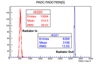
| + | |6320 || '''390''' nm Pass filter, signal at ADC channel 500, radiator in | ||
| + | |- | ||
| + | |6321 || 390 nm Pass filter, signal at ADC channel 500, radiator '''OUT''', [[File:TellerLight_390nm_5-24-17.png | 200 px]] | ||
| + | |- | ||
| + | |6322 || '''320 nm''' Pass filter, signal at ADC channel 500, radiator OUT, peak at ADC chan 3200 like 390 nm filter | ||
| + | |- | ||
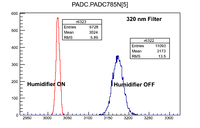
| + | |6323 || "cold air humidifier ON', 320 nm Pass filter, signal at ADC channel 500, radiator OUT, peak at ADC chan 3200 like 390 nm filter, [[File:TellerLight_6323_320nm_5-24-17.png | 200 px]] | ||
| + | |- | ||
| + | |6324 || cold air humidifier '''OFF''', 320 nm Pass filter, signal at ADC channel 500, radiator OUT, | ||
| + | |- | ||
| + | |6325 || cold air humidifier '''ON''', 320 nm Pass filter, signal at ADC channel 500, radiator OUT, beam current 150 mV in 1 Meg Ohm | ||
| + | |- | ||
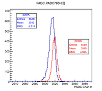
| + | |6326 || cold air humidifier '''OFF''', 320 nm Pass filter, signal at ADC channel 500, radiator OUT, beam current 150 mV in 1 Meg Ohm, [[File:TellerLight_6326_320nm_5-24-17.png | 200 px]] | ||
| + | |} | ||
| + | |||
| + | the He-3 rate definitely increases during the irradiation (probably due to Hall Activity increasing) | ||
| + | ==5/25/17== | ||
| + | |||
| + | 32 MeV Beam 150 mA current 100 ns wide beam no beam stop | ||
| + | |||
| + | The He-3 tube is plugged into a scaler that counts all pulses (not just the ones during the beam gate). | ||
| + | |||
| + | {| border="3" cellpadding="5" cellspacing="0" | ||
| + | | Run# || Configuration | ||
| + | |- | ||
| + | |6346 || '''320''' nm Pass filter | ||
| + | |- | ||
| + | |6347 || '''320''' nm Pass filter, changed pulse width between 100 and 800 ns | ||
| + | |- | ||
| + | |6348 || 320 nm Pass filter, change amplitude | ||
| + | |- | ||
| + | |6353 ||'''320 nm Pass filter plus UV filter PMT small aperture in the hole, change beam current from 100 to 200 to check normalization''' | ||
| + | |- | ||
| + | |6354 || '''320''' nm Pass filter, plus UV filter PMT small aperture in the hole | ||
| + | |- | ||
| + | |6355 || '''320 & 330''' nm Pass filter, plus UV filter PMT small aperature in the hole | ||
| + | |- | ||
| + | |6356 || '''390''' nm Pass filter, plus UV filter PMT small aperture in the hole, [[File:TellerLight_6356_5-25-17.png | 200 px]] | ||
| + | |- | ||
| + | |6357 || '''390''' nm Pass filter, plus UV filter PMT small aperture in the hole, No change | ||
| + | |- | ||
| + | |6358 || '''390+320''' nm Pass filter, plus UV filter PMT small aperture in the hole, | ||
| + | |- | ||
| + | |6359 || '''390''' nm Pass filter, plus UV filter PMT small aperture in the hole, Reproducibility check | ||
| + | |- | ||
| + | |6360 || 390 nm Pass filter, plus UV filter PMT small aperture in the hole, increase current from 150 to 200 mA | ||
| + | |- | ||
| + | |6361 || 390 nm Pass filter, plus UV filter PMT small aperture in the hole, current 150 mA, mister '''ON''' | ||
| + | |- | ||
| + | |6362 || 390 nm Pass filter, plus UV filter PMT small aperture in the hole, current 150 mA, mister '''OFF''' | ||
| + | |} | ||
| + | |||
| + | |||
| + | ==PMT linearity test== | ||
| + | |||
| + | PMT[5] = PMT in the cell looking at the mirror | ||
| + | |||
| + | Suspect PMT was linearly responding to beam current at 50 ns widths and 75 mA peak, 32 MeV | ||
| + | |||
| + | {| border="3" cellpadding="5" cellspacing="0" | ||
| + | | Run# || Current (nV*sec) || PMT[5](PADC chann #) || PMT[5] Fstop | ||
| + | |- | ||
| + | |6377 ||3.8 || || | ||
| + | |- | ||
| + | |6378 ||'''8.5''' || 1600 || Cut wide pulse current in half and shortened pulse to 50 ns, pulse very hard to measure at 50 ns | ||
| + | |- | ||
| + | |6379 ||'''2.2''' ||837 || current changed during run | ||
| + | |- | ||
| + | |6380 ||'''3.5''' ||1200 || [[File:TelLin_5-25-17.png | 200 px]] | ||
| + | |- | ||
| + | |6381 || 4.3|| 704|| Position 1=open, at position '''3''', diameter = 26 mm | ||
| + | |- | ||
| + | |6382 || 4.5||190 || Position 1=open, at position '''6''' diameter=3.5 mm | ||
| + | |- | ||
| + | |6383 ||4.7 ||1214 || Position 1=open, at position '''1''' diameter = 31 mm | ||
| + | |- | ||
| + | |6384 || ||1237 || Position 1=open, at position 1, double width to 100 ns | ||
| + | |- | ||
| + | |6385 || ||1237 || Position 1=open, at position 1, double width to 200 ns (ADC overflow!) | ||
| + | |- | ||
| + | |} | ||
| + | |||
| + | == Current calibration== | ||
| + | Changed beam current using width of the beam | ||
| + | |||
| + | {| border="3" cellpadding="5" cellspacing="0" | ||
| + | | Run# || Charge || PADC Chann# || Configuration | ||
| + | |- | ||
| + | |6337 ||<math>10 \times \frac{1.47 \times 10^{-6}}{50} = 0.294</math> uC||3625 <math>\pm</math> 26 || current calibration, 1.47 uV*sec in 50 Ohms, 2.2 usec, x10 attenuator | ||
| + | |- | ||
| + | |6338 || 0.1588 || 2098 <math>\pm</math> 6|| current calibration, 794 nV*sec in 50 Ohms, 1.1 usec, x10 attenuator | ||
| + | |- | ||
| + | |6339 || 0.058 ||1093 <math>\pm</math> 4.7 || current calibration, 429 nV*sec in 50 Ohms, 550 nsec, x10 attenuator | ||
| + | |- | ||
| + | |6340 ||0.0378 || 504<math>\pm</math> 4 || current calibration, 189 nV*sec in 50 Ohms, 225 nsec, x10 attenuator | ||
| + | |- | ||
| + | |6341 ||0.0208 || 342 <math>\pm</math> 3 || current calibration, 104 nV*sec in 50 Ohms, 125 nsec, x10 attenuator | ||
| + | |} | ||
| + | |||
| + | slope=8.53252e-05 +/- 6.47968e-06 | ||
| + | y-intercept=-0.0189951 +/- 0.0141188 | ||
| + | |||
| + | |||
| + | Micro-Coulombs (uC) | ||
| + | |||
| + | FF->Draw("PADC.PADC785N[1]*8.53252e-05>>r6338(5000,0,1)"); | ||
| + | |||
| + | |||
| + | |||
| + | {| border="3" cellpadding="5" cellspacing="0" | ||
| + | | Run# || Charge || PADC Chann# || Configuration | ||
| + | |- | ||
| + | |6366 ||<math> \times \frac{330 \times 10^{-9}}{10^6} = 0.294</math> uC||1351 <math>\pm</math> 14 || current calibration, 330 \pm 5 uV*sec in 1 Meg Ohms, 2.2 usec, | ||
| + | |- | ||
| + | |6367 || || 792 <math>\pm</math> 9|| current calibration, 190 \pm 5 nV*sec in 1 M Ohms, 2.2usec | ||
| + | |- | ||
| + | |6368 || || 496 <math>\pm</math> 5 || current calibration, 106 \pm 3 nV*sec in 1 M Ohms, 2.2usec | ||
| + | |- | ||
| + | |6371|| || 1066 <math>\pm</math> 10 || current calibration, 265 \pm 4 nV*sec in 1 M Ohms, 2.2usec | ||
| + | |- | ||
| + | |} | ||
| + | |||
| + | |||
| + | ==5/26/17== | ||
| + | |||
| + | 32 MeV Beam 150 mA current | ||
| + | |||
| + | UV wide band filter on cell PMT, Aperature wide open | ||
| + | |||
| + | {| border="3" cellpadding="5" cellspacing="0" | ||
| + | | Run# || Cell PMT [5] || FC [7] | ||
| + | |- | ||
| + | |6389 ||3142 || 1509 | ||
| + | |- | ||
| + | |6390 || 2231|| 908 | ||
| + | |- | ||
| + | |6391 ||1191 || 447 | ||
| + | |- | ||
| + | |6392 ||708 || 287 (have full current near end) | ||
| + | |- | ||
| + | |6393 ||2642 || 1147 | ||
| + | |- | ||
| + | |6394 ||1605 || 580 | ||
| + | |- | ||
| + | |6395 ||1889 || 696 (changed current near end of run) | ||
| + | |- | ||
| + | |6396 ||698 || 279 | ||
| + | |- | ||
| + | |6397 ||390 || 183 (changed current near end of run) | ||
| + | |} | ||
| + | |||
| + | |||
| + | filters on cell PMT, NO Aperature, Mixed field (taken during irradiation) | ||
| + | |||
| + | {| border="3" cellpadding="5" cellspacing="0" | ||
| + | | Run# || Cell PMT [5] || FC [7] || [5]/[7] || comment | ||
| + | |- | ||
| + | |6401 ||3503 || 1743 || 2.0 ||320 nm filer | ||
| + | |- | ||
| + | |6402 ||110 || 1614 || 0.07 || 330 + 320 nm filters | ||
| + | |- | ||
| + | |6403 ||2972 ||1519 || 1.956 || 390 nm Filter | ||
| + | |} | ||
| + | |||
| + | data below shows two regions of linearity | ||
| + | root [6] FF->Draw("PADC.PADC785N[5]/PADC.PADC785N[7]"); | ||
| + | root [7] FF->Draw("PADC.PADC785N[7]","PADC.PADC785N[5]/PADC.PADC785N[7]<2"); | ||
| + | root [8] FF->Draw("PADC.PADC785N[7]","PADC.PADC785N[5]/PADC.PADC785N[7]>2"); | ||
| + | |||
| + | |||
| + | {| border="3" cellpadding="5" cellspacing="0" | ||
| + | | Run# || Cell PMT [5] || FC [7] | ||
| + | |- | ||
| + | |6403 ||2972 ||1519 | ||
| + | |- | ||
| + | |6404 || 2017 || 894 | ||
| + | |- | ||
| + | |6405 || 1259 || 526 | ||
| + | |- | ||
| + | |6406 || 758 || 332 | ||
| + | |- | ||
| + | |6407 || 422 || 209 | ||
| + | |- | ||
| + | |6408 ||2620 || 1312 | ||
| + | |- | ||
| + | |6409 || 1657|| 702 | ||
| + | |- | ||
| + | |6410 ||934 || 398 | ||
| + | |- | ||
| + | |6411 ||549 || 254 | ||
| + | |} | ||
| + | |||
| + | |||
| + | {| border="3" cellpadding="5" cellspacing="0" | ||
| + | | Run# || Cell PMT [5] / FC [7] || Mist | ||
| + | |- | ||
| + | |6411 ||2.15 || Off | ||
| + | |- | ||
| + | |6413 || 1.951 || ON | ||
| + | |- | ||
| + | |6414 || 1.944 || Off | ||
| + | |- | ||
| + | |6415 || || On | ||
| + | |} | ||
| + | |||
| + | [[2nCor 44| go_back]] | ||
| + | |||
| + | [[2nCor_44#Equipment]] | ||
Latest revision as of 18:41, 26 May 2017
Analog Signals
He3 Tube neutron detectors are 52 cm long and 1.5 cm radius cylinders, 1200 Volts with EG&G (ortec) pre amp Model 142PC (Serial #787)
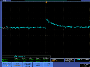
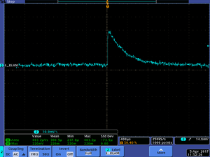
Although 1200 Volts is applied to the Ortec Preamp, only 350 Volts is established on the "input" port where the Tube is plugged in. If 1250 Volts is applied, then 366 Volts is observed.
For the TENNELEC you need to apply 1650 Volts to get 362 applied to the Tube
The TENNELEC signal output at 1550 Volts has less noise with signal at about 30 mV compared to the output of the ortec. There is a230 mV DC offset on the output
Output measured by CAEN V785N Peaks sensing ADC
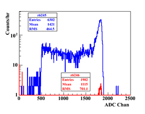
Using a Cf-252 source positions on a shelf below the He-3 tube covered by 2" thick virgin Poly and set to 1250 Volts. Using Ortec pre-amp 142PC serial # 787.
The Timing output of the preamp was sent to an Ortec Timing filter amplifier to be inverted. The Gain was set to x10 and the integrate set to 20 ns.
The Energy output was sent to an Ortec Spectroscopy amplifier model 672. The gain was set to x10 and the shaping time set to 2usec.
Run 6245 has a Cf-252 source place on a shelf approximately 80 cm below the He-3 tube that had been encased in 2" thick virgin poly.
Run 6246 recorded the background observed without the source over a 19 hour period.
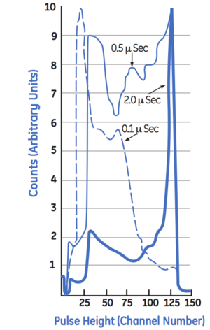
The expectation from File:GE ReuterStokes.pdf is
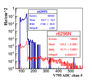
Performed another measurement of the He-3 tube using the Cf-252 source. I used the bipolar output of the ORTEC spec AMP model 672. The He-3 tube is surrounded by a 2" thick layer of virgin poly. The virgin poly is then encased in a 2" layer of lead. The Cf-252 source was placed directly on top of the lead. Below is a measurement recorded in run #6295 taken over a 7 minute period Run #6596 was taken over a three day period.
If I normalize the rate per cm^2 of detector (project the cylinder to a 52 cm x 3 cm rectangle = 156 cm^2)
Cosmic rays produce 10^{3}/cm^2/sec
PAA->Draw("PADC785N[3]>>r6296N(500,0,1000)",".00000002473");
PAA->Draw("PADC785N[3]>>r6295N(500,0,1000)",".000015263");
Beam Tests
5/16/17: 44 MeV machine was being tuned at 2 MeV so I used the nCorHe3 configuration to look at the He-3 output when there shouldn't be neutrons in the Hall.
Run 6297: Timing AMp =2 Postamp to PADC set to gain of 10
Run 6298: Timing AMp=2 Postamp to PADC set to gain of 50
Run 6299: Timing AMp=adjusting during run Postamp to PADC set to gain of 50
Run 6300: Timing AMp=8 Postamp to PADC set to gain of 50
A CFD threshold of -181 mV will keep the He-3 tube timing amp from firing when the 44 MeV machine is running. The Cf-252 source rate was 200 +/- 40 Hz at this CFD setting.
For ADC do
FF->Draw("PADC.PADC785N[3]>>(500,0,1000)");
For TDC (Window is 1500 nsec wide)
FF->Draw("(TDC.TDC1190[1][28]-TDC.TDC1190[1][31])*0.1")
Check Timing with FF->Draw("(TDC.TDC1190[2][31]-TDC.TDC1190[1][31])*0.1")
The above should be about 200 ns
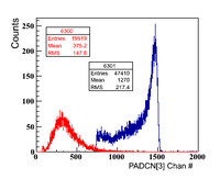
Run 6301, ran in PAA configuration with Cf 252 source on top of detector
PAA->Draw("PADC.PADC785N[3]>>r6301(2000,0,2000)")
5/23/17
32 MeV Beam 50 mA current
The He-3 tube is plugged into a scaler that counts all pulses (not just the ones during the beam gate).
| Run# | Configuration |
| 6310 | 710 +/- 20 Hz neutron rate during first 15 minutes, then 870 +/- 20 Hz neutron rate during second 15 minutes, UV broadband pass filter |
| 6311 | 840 +/- 20 Hz neutron rate during first 15 minutes, then Hz neutron rate during second 15 minutes, 390 nm Filter |
| 6313 | 390 nm Filter, HV = 1800 ( the HV has changed from run 6311) |
| 6314 | 320 nm Filter |
| 6315 | 320 + 330 nm Filter |
the He-3 rate definitely increases during the irradiation (probably due to Hall Activity increasing)
5/24/17
32 MeV Beam 150 mA current 100 ns wide beam no beam stop, 4 mm thick (12 g) Yttrium in.
The He-3 tube is plugged into a scaler that counts all pulses (not just the ones during the beam gate).
2.54 mm Tungsten radiator
the He-3 rate definitely increases during the irradiation (probably due to Hall Activity increasing)
5/25/17
32 MeV Beam 150 mA current 100 ns wide beam no beam stop
The He-3 tube is plugged into a scaler that counts all pulses (not just the ones during the beam gate).
PMT linearity test
PMT[5] = PMT in the cell looking at the mirror
Suspect PMT was linearly responding to beam current at 50 ns widths and 75 mA peak, 32 MeV
Current calibration
Changed beam current using width of the beam
| Run# | Charge | PADC Chann# | Configuration |
| 6337 | uC | 3625 26 | current calibration, 1.47 uV*sec in 50 Ohms, 2.2 usec, x10 attenuator |
| 6338 | 0.1588 | 2098 6 | current calibration, 794 nV*sec in 50 Ohms, 1.1 usec, x10 attenuator |
| 6339 | 0.058 | 1093 4.7 | current calibration, 429 nV*sec in 50 Ohms, 550 nsec, x10 attenuator |
| 6340 | 0.0378 | 504 4 | current calibration, 189 nV*sec in 50 Ohms, 225 nsec, x10 attenuator |
| 6341 | 0.0208 | 342 3 | current calibration, 104 nV*sec in 50 Ohms, 125 nsec, x10 attenuator |
slope=8.53252e-05 +/- 6.47968e-06 y-intercept=-0.0189951 +/- 0.0141188
Micro-Coulombs (uC)
FF->Draw("PADC.PADC785N[1]*8.53252e-05>>r6338(5000,0,1)");
| Run# | Charge | PADC Chann# | Configuration |
| 6366 | uC | 1351 14 | current calibration, 330 \pm 5 uV*sec in 1 Meg Ohms, 2.2 usec, |
| 6367 | 792 9 | current calibration, 190 \pm 5 nV*sec in 1 M Ohms, 2.2usec | |
| 6368 | 496 5 | current calibration, 106 \pm 3 nV*sec in 1 M Ohms, 2.2usec | |
| 6371 | 1066 10 | current calibration, 265 \pm 4 nV*sec in 1 M Ohms, 2.2usec |
5/26/17
32 MeV Beam 150 mA current
UV wide band filter on cell PMT, Aperature wide open
| Run# | Cell PMT [5] | FC [7] |
| 6389 | 3142 | 1509 |
| 6390 | 2231 | 908 |
| 6391 | 1191 | 447 |
| 6392 | 708 | 287 (have full current near end) |
| 6393 | 2642 | 1147 |
| 6394 | 1605 | 580 |
| 6395 | 1889 | 696 (changed current near end of run) |
| 6396 | 698 | 279 |
| 6397 | 390 | 183 (changed current near end of run) |
filters on cell PMT, NO Aperature, Mixed field (taken during irradiation)
| Run# | Cell PMT [5] | FC [7] | [5]/[7] | comment |
| 6401 | 3503 | 1743 | 2.0 | 320 nm filer |
| 6402 | 110 | 1614 | 0.07 | 330 + 320 nm filters |
| 6403 | 2972 | 1519 | 1.956 | 390 nm Filter |
data below shows two regions of linearity root [6] FF->Draw("PADC.PADC785N[5]/PADC.PADC785N[7]"); root [7] FF->Draw("PADC.PADC785N[7]","PADC.PADC785N[5]/PADC.PADC785N[7]<2"); root [8] FF->Draw("PADC.PADC785N[7]","PADC.PADC785N[5]/PADC.PADC785N[7]>2");
| Run# | Cell PMT [5] | FC [7] |
| 6403 | 2972 | 1519 |
| 6404 | 2017 | 894 |
| 6405 | 1259 | 526 |
| 6406 | 758 | 332 |
| 6407 | 422 | 209 |
| 6408 | 2620 | 1312 |
| 6409 | 1657 | 702 |
| 6410 | 934 | 398 |
| 6411 | 549 | 254 |
| Run# | Cell PMT [5] / FC [7] | Mist |
| 6411 | 2.15 | Off |
| 6413 | 1.951 | ON |
| 6414 | 1.944 | Off |
| 6415 | On |
