Difference between revisions of "LB RunGroupC Vertex"
| Line 204: | Line 204: | ||
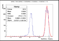
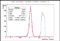
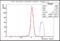
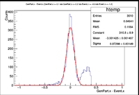
! || [0.9 , 1.0] || [0.8 , 0.9] || [0.7 , 0.8] || [0.6 , 0.7] || [0.5 , 0.6] || [0.4 , 0.5] || [0.3 , 0.4] || [0.2 , 0.3] || [0.1 , 0.2] || [0.0 , 0.1] | ! || [0.9 , 1.0] || [0.8 , 0.9] || [0.7 , 0.8] || [0.6 , 0.7] || [0.5 , 0.6] || [0.4 , 0.5] || [0.3 , 0.4] || [0.2 , 0.3] || [0.1 , 0.2] || [0.0 , 0.1] | ||
|- | |- | ||
| − | || Resolution (cm) || || || || || || || 0.06196 +/- 0.00146 || 0.06087 +/- 0.00114 || 0.07298 +/- 0.00149 || 0.09017 +/- 0.00128 | + | || Resolution (cm) || || || || || || 0.07271 +/- 0.00159 || 0.06196 +/- 0.00146 || 0.06087 +/- 0.00114 || 0.07298 +/- 0.00149 || 0.09017 +/- 0.00128 |
|- | |- | ||
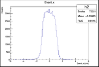
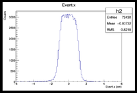
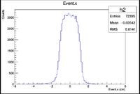
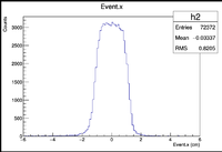
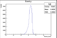
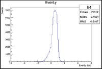
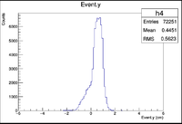
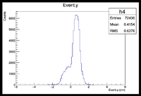
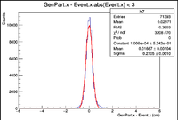
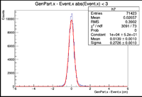
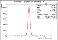
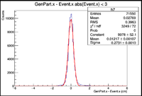
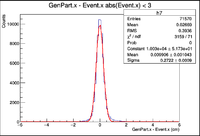
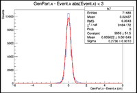
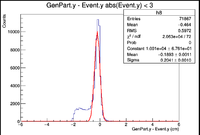
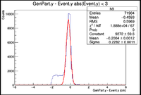
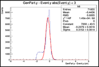
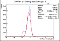
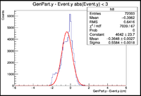
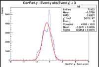
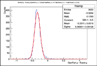
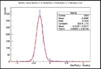
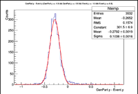
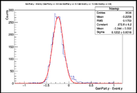
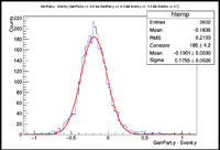
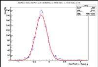
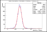
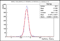
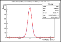
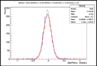
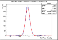
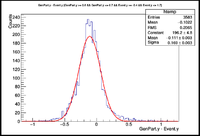
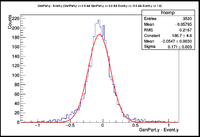
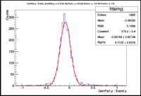
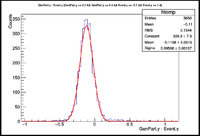
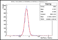
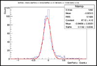
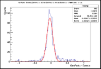
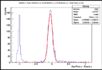
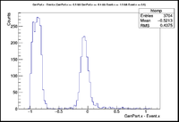
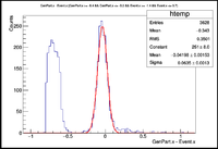
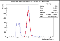
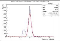
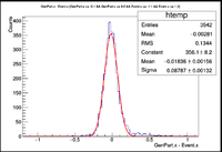
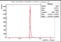
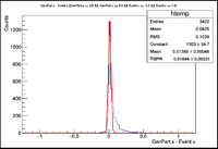
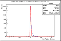
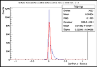
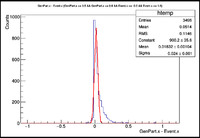
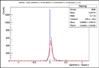
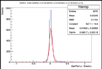
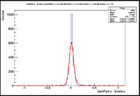
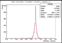
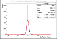
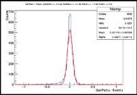
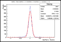
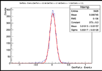
|| Vx Difference || || || || || || [[File:VxDiff-0.4,0.5- 270Deg.png|200px]] || [[File:VxDiff-0.3,0.4- 270Deg.png|200px]] || [[File:VxDiff-0.2,0.3- 270Deg.png|200px]] || [[File:VxDiff-0.1,0.2- 270Deg.png|200px]] || [[File:VxDiff-0.0,0.1- 270Deg.png|200px]] | || Vx Difference || || || || || || [[File:VxDiff-0.4,0.5- 270Deg.png|200px]] || [[File:VxDiff-0.3,0.4- 270Deg.png|200px]] || [[File:VxDiff-0.2,0.3- 270Deg.png|200px]] || [[File:VxDiff-0.1,0.2- 270Deg.png|200px]] || [[File:VxDiff-0.0,0.1- 270Deg.png|200px]] | ||
Revision as of 18:51, 2 August 2016
Vertex Reconstruction studies
Inclusive electron GEMC 2.4 & Coatjava 2.4
Summary
Set all histogram ranges to -6,6 cm and bin sizes of 0.1 cm
Point target X,Y,Z=0 cm
| No Rastering | |
|---|---|
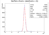
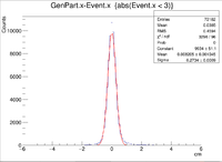
| Vx Difference | 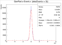
|
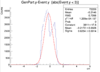
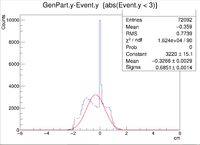
| Vy Difference | 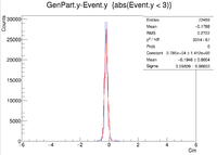
|
| Vz Difference | 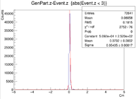
|
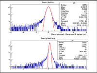
| X Resolution (cm) | 0.2362 +/- 0.0008 |
| Y Resolution(cm) | 0.09809 +/- 0.00033 |
| Z Resolution (cm) | 0.05435 +/- 0.00017 |
These histograms raise some questions. To begin I created a LUND file with 6 GeV incident electrons at 25 degrees in theta and 0 degrees in phi. All of the vertex positions were set to 0. I then ran GEMC 2.4 using the command line ~/src/CLAS/GEMC/source/gemc -USE_GUI=0 -INPUT_GEN_FILE="LUND,No_Raster.LUND" -N=75000 eg12_sol_No_Raster.gcard
which created an output file called eg12_sol_75k_No_Raster.ev. After that the reconstruction command line used was
~/src/CLAS/coatjava-2.4/bin/clas12-reconstruction -i eg12_sol_75k_No_Raster.ev-config GEOM::new=true -config MAG::torus=-1.0 -config MAG::solenoid=1.0 -o eg12_sol_75k_No_Raster_rec.evio -s DCHB:DCTB:EC:FTOF:EB -config DATA::mc=true -config DCTB::useRaster=true
After the reconstruction a root file was created using
~/src/CLAS/evio2root/bin/evio2root eg12_sol_75k_No_Raster_rec.evio eg12_sol_75k_No_Raster_rec.root 75000
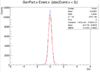
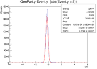
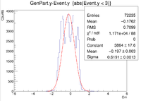
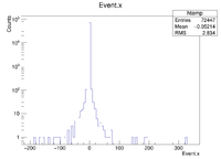
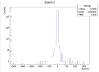
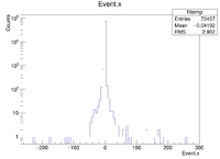
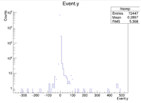
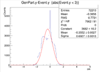
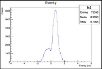
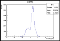
A plot was then created to show the X Vertex and Y Vertex Differences
The first question is why is there a shift in the Y Difference. What would make X more centered around 0? The next question is when rastering begins, why do the resolutions in the X Vertices remain unchanged while the resolutions in the Y Vertices change?
Point in 2-D but extended target in 1-D
Two vertex variables are fixed at zero and the third vertex variable is altered
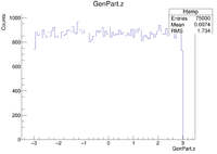
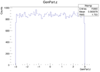
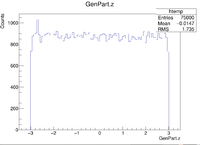
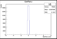
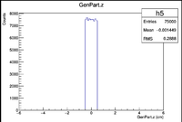
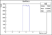
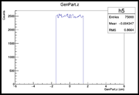
Extended target -3 < Z < 3 cm
Extended target in Z. Vy shift analysis
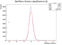
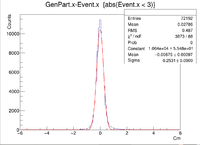
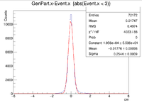
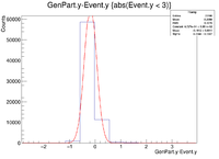
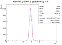
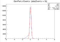
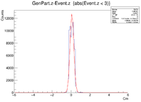
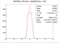
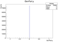
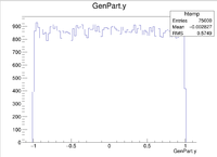
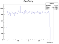
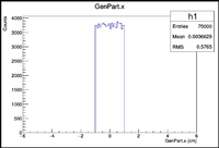
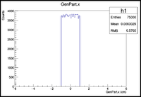
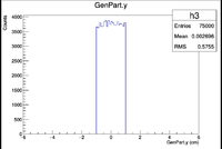
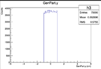
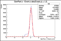
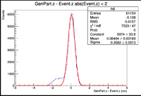
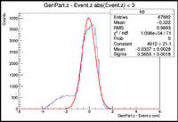
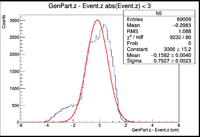
All Histograms below were created by simply making the target longer along the Z axis. Each case uses vertex points for X and Y ranging from -1cm to 1cm
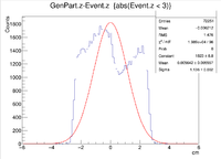
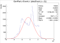
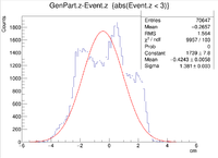
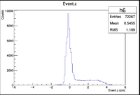
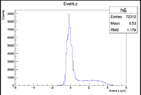
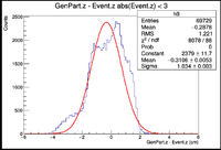
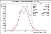
It would seem that increasing the length of the target in the Z direction has an effect on the resolution of the Y vertex position along with how far the center of the Gaussian peak will shift for the Y vertex differences.
Localized Vertex Resolution Investigation of Line Targets
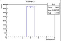
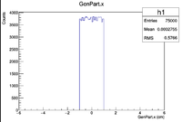
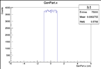
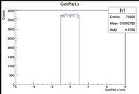
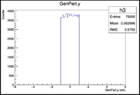
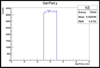
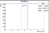
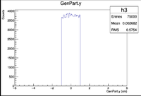
GEMC was ran to create electrons being produced in a line along certain axes. These include three separate 2cm targets centered at (0,0,0) in the X, Y , and Z directions. The final target is a line along the Z axis centered at (0,0,0) that is 6cm long. The generated electrons were shot at 25 degrees in theta and 0 degrees in phi at an energy of 6GeV.
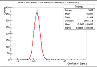
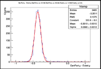
Here is an example of how the cuts were made. Consider the case of a 2cm line target in the Z direction centered at (0,0,0). Closed intervals begin at the end of the target and are 0.1cm long. So the first interval would be [-1.0,-0.9], then the next would be [-0.9, -0.8] and so on until the entire target is covered. The events in the EVENTHB bank were cut so that in any given interval there would be a margin of +/- 1cm to remove any outliers that may cause the histograms to have long tails.
Below are the histograms for the 2cm line target in Y,X=0,Z=0
Below are the Histograms for a 2cm long target in the X Direction with a 6GeV electron fired at 25 degrees in theta and 90 degrees in phi
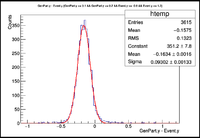
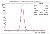
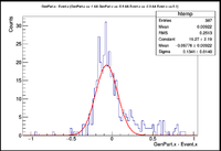
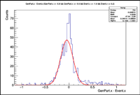
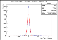
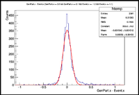
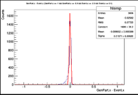
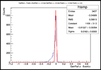
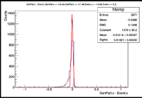
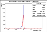
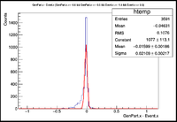
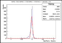
Below are the Vx Differences using a 2cm target in X with incident 6 GeV electrons at 25 degrees in theta and 270 degrees in phi
Elastic electron proton GEMC 2.4 & Coatjava 2.4
References
https://clasweb.jlab.org/wiki/index.php/TF_EG12_Vertex#Z_resolution_With_micro-megas
