Difference between revisions of "TF EIMLab13 Writeup"
| (17 intermediate revisions by the same user not shown) | |||
| Line 8: | Line 8: | ||
| − | Using 2N3904 is more | + | Using 2N3904 is more straight forward in this lab. |
=Transistor circuit= | =Transistor circuit= | ||
| + | |||
| + | '''Used to npn 2N3904 transister''' | ||
| + | |||
1.) Identify the type (n-p-n or p-n-p) of transistor you are using and fill in the following specifications. | 1.) Identify the type (n-p-n or p-n-p) of transistor you are using and fill in the following specifications. | ||
| Line 18: | Line 21: | ||
|Value || Description | |Value || Description | ||
|- | |- | ||
| − | | || Collector-Base breakdown voltage | + | |40 V || Collector-Base breakdown voltage |
|- | |- | ||
| − | | || Emitter-Base Breakdown Voltage | + | | 6 V|| Emitter-Base Breakdown Voltage |
|- | |- | ||
| − | | || Maximum Collector Voltage | + | | 40|| Maximum Collector Voltage |
|- | |- | ||
| − | | || Maximum Collector Current | + | |200 mA || Maximum Collector Current |
|- | |- | ||
| − | | || Transistor Power rating(<math>P_{Max}</math>) | + | | 625 mW || Transistor Power rating(<math>P_{Max}</math>) |
|- | |- | ||
| − | | || DC current gain <math>h_{FE}( I_C, V_{CE})</math> | + | |30 - 300 || DC current gain <math>h_{FE}( I_C, V_{CE})</math> |
|} | |} | ||
| Line 38: | Line 41: | ||
| − | Let R_E = 100 \Omega. | + | Let <math>R_E = 100 \Omega</math>. |
| − | V_{CC} | + | <math>V_{CC} < 5 Volts</math> variable power supply |
| − | V_{BE}= 1V. | + | <math>V_{BE}= 1V</math>. |
| − | I_B = 2 \mu A = 1V/500 k \Omega | + | I_B = 2<math> \mu</math> A = 1V/500 k<math> \Omega</math> |
| − | : = 5 \mu A = 1V/200 k \Omega | + | : = 5<math> \mu</math> A = 1V/200 k <math>\Omega</math> |
| − | : = 10 \mu A = 1V/100 k \Omega | + | : = 10 <math>\mu A</math> = 1V/100 k <math>\Omega</math> |
| − | 3.) Measure the emitter current <math>I_E</math> for several values of <math>V_{CE}</math> by changing <math>V_{CC}</math> such that the base current <math>I_B = 2 \mu</math> A is constant. <math>I_B \approx \frac{V_{ | + | 3.) Measure the emitter current <math>I_E</math> for several values of <math>V_{CE}</math> by changing <math>V_{CC}</math> such that the base current <math>I_B = 2 \mu</math> A is constant. <math>I_B \approx \frac{V_{BB}-V_{b}}{R_B}</math> |
| + | <math>R_{B} = 500 k \Omega</math> | ||
| + | |||
| + | <math>R_{E} = 101 \Omega</math> | ||
{| border="1" |cellpadding="20" cellspacing="0 | {| border="1" |cellpadding="20" cellspacing="0 | ||
|- | |- | ||
| − | |V_{ | + | |<math>V_{BB} -V_B</math> || <math>I_B</math> || <math>V_{CC}</math> ||<math> V_ E</math> || <math>I_E</math> |
| + | |- | ||
| + | |V || <math>\mu</math> A || V || mV || mA | ||
| + | |- | ||
| + | |1.007 || 2|| 0.0704 ||1.2 || | ||
| + | |- | ||
| + | |1.05 ||2 ||0.110 ||4.9 || | ||
| + | |- | ||
| + | |1.02 ||2 ||0.133 ||8.9 || | ||
| + | |- | ||
| + | |1.002 ||2 ||0.162 ||15.7 || | ||
| + | |- | ||
| + | | 1.002||2 ||0.184 ||21.1 || | ||
| + | |- | ||
| + | |1.026 ||2 ||0.2287 ||32.3 || | ||
|- | |- | ||
| − | | | + | | 1.012||2 ||0.3157 || 39.5 || |
|- | |- | ||
| − | | | + | |1.008 ||2 ||0.484 || 40.0|| |
|- | |- | ||
| − | | || || || | + | | 1.008||2 ||1.023 || 40.3 |
|- | |- | ||
| − | | || || || | + | |1.008 ||2 ||2.167 || 40.7 |
|- | |- | ||
| − | | || || || | + | |1.008 ||2 ||2.960 || 40.8 |
|- | |- | ||
| − | | || || || | + | |1.008 ||2 ||5.00 || 41.2 |
|- | |- | ||
| − | + | | || || || | |
|} | |} | ||
| Line 74: | Line 94: | ||
4.) Repeat the previous measurements for <math>I_B \approx 5 \mbox{ and } 10 \mu</math> A. Remember to keep <math>I_CV_{CE} < P_{max}</math> so the transistor doesn't burn out | 4.) Repeat the previous measurements for <math>I_B \approx 5 \mbox{ and } 10 \mu</math> A. Remember to keep <math>I_CV_{CE} < P_{max}</math> so the transistor doesn't burn out | ||
| + | |||
| + | <math>R_{B} = 201.8 k \Omega</math> | ||
| + | |||
| + | {| border="1" |cellpadding="20" cellspacing="0 | ||
| + | |- | ||
| + | |<math>V_{BB} -V_B</math> || <math>I_B</math> || <math>V_{CC}</math> ||<math> V_ E</math> || <math>I_E</math> | ||
| + | |- | ||
| + | |V || <math>\mu</math> A || V || mV || mA | ||
| + | |- | ||
| + | |1.044 || 5|| 0.094 ||7 || | ||
| + | |- | ||
| + | |1.053 || 5||0.134 ||19 || | ||
| + | |- | ||
| + | |1.026 || 5|| 0.167 || 32|| | ||
| + | |- | ||
| + | |1.003 || 5|| 0.200 || 47|| | ||
| + | |- | ||
| + | |1.003 || 5|| 0.234 ||62 || | ||
| + | |- | ||
| + | |1.02 || 5|| 0.269 ||77 || | ||
| + | |- | ||
| + | |1.0 || 5|| 0.289 ||83 || | ||
| + | |- | ||
| + | |1.07 || 5|| 0.442 ||101 || | ||
| + | |- | ||
| + | |1.02 || 5|| 0.721 ||99 || | ||
| + | |- | ||
| + | |1.02 || 5|| 1.04 ||100 || | ||
| + | |- | ||
| + | |1.02 || 5|| 1.94 ||100 || | ||
| + | |- | ||
| + | |1.02 || 5|| 2.96 ||101 || | ||
| + | |- | ||
| + | |1.02 || 5|| 3.72 ||102 || | ||
| + | |- | ||
| + | |} | ||
| + | |||
| + | <math>R_{B} = 100 k \Omega</math> | ||
{| border="1" |cellpadding="20" cellspacing="0 | {| border="1" |cellpadding="20" cellspacing="0 | ||
|- | |- | ||
| − | |V_{ | + | |<math>V_{BB} -V_B</math> || <math>I_B</math> || <math>V_{CC}</math> ||<math> V_ E</math> || <math>I_E</math> |
| + | |- | ||
| + | |V || <math>\mu</math> A || V || mV || mA | ||
| + | |- | ||
| + | |0.942 || 10|| 0.227 ||78.1 || | ||
| + | |- | ||
| + | |1.005 || 10|| 0.245 ||94 || | ||
| + | |- | ||
| + | | 0.995|| 10|| 0.267 ||108 || | ||
|- | |- | ||
| − | | | + | | 1.068|| 10||0.31 ||138 || |
|- | |- | ||
| − | | | + | |1.005 || 10|| 0.355 ||160 || |
|- | |- | ||
| − | | || || || || | + | | 0.996|| 10|| 1.032||197 || |
|- | |- | ||
| − | | || || || || | + | |1.002 || 10|| 0.688 ||197 || |
|- | |- | ||
| − | | || || || || | + | |0.996|| 10|| 2.175 || 199|| |
|- | |- | ||
| − | | || || || || | + | |0.994 || 10||3.283 || 200|| |
|- | |- | ||
| − | | || || || || | + | | 0.992|| 10||4.66 ||202 || |
|- | |- | ||
| − | |||
|} | |} | ||
| + | |||
5.) Graph <math>I_C</math> -vs- <math>V_{CE}</math> for each value of <math>I_B</math> and <math>V_{CC}</math> above. (40 pnts) | 5.) Graph <math>I_C</math> -vs- <math>V_{CE}</math> for each value of <math>I_B</math> and <math>V_{CC}</math> above. (40 pnts) | ||
| + | |||
| + | [[File:TF_Ic-vs-VccEIM_Lab13.png]] | ||
6.) Overlay points from the transistor's data sheet on the graph in part 5.).(10 pnts) | 6.) Overlay points from the transistor's data sheet on the graph in part 5.).(10 pnts) | ||
| Line 104: | Line 172: | ||
=Questions= | =Questions= | ||
| − | + | 1.)Compare your measured value of <math>h_{FE}</math> or <math>\beta</math> for the transistor to the spec sheet? (10 pnts) | |
| − | + | :<math>\beta = \frac{I_C}{I_B} = \frac{0.5 mA}{0.002 mA} = 250</math> | |
| − | + | 2.)What is <math>\alpha</math> for the transistor?(10 pnts) | |
| − | + | ||
| − | + | 3.)The base must always be more _________(________) than the emitter for a npn (pnp)transistor to conduct I_C.(10 pnts) | |
| + | |||
| + | 4.)For a transistor to conduct I_C the base-emitter junction must be ____forward_______ biased.(10 pnts) | ||
| + | |||
| + | 5.)For a transistor to conduct I_C the collector-base junction must be ______reverse_____ biased.(10 pnts) | ||
[[Forest_Electronic_Instrumentation_and_Measurement]] | [[Forest_Electronic_Instrumentation_and_Measurement]] | ||
Latest revision as of 23:57, 2 April 2015
DC Bipolar Transistor Curves
Data sheet for transistors.
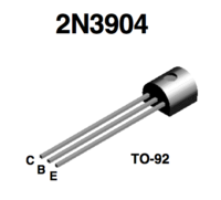
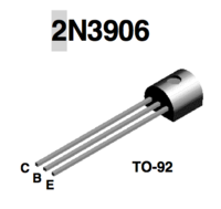
Media:2N3904.pdfMedia:2N3906.pdf
Using 2N3904 is more straight forward in this lab.
Transistor circuit
Used to npn 2N3904 transister
1.) Identify the type (n-p-n or p-n-p) of transistor you are using and fill in the following specifications.
| Value | Description |
| 40 V | Collector-Base breakdown voltage |
| 6 V | Emitter-Base Breakdown Voltage |
| 40 | Maximum Collector Voltage |
| 200 mA | Maximum Collector Current |
| 625 mW | Transistor Power rating() |
| 30 - 300 | DC current gain |
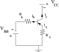
2.) Construct the circuit below according to the type of transistor you have.
Let .
variable power supply
.
I_B = 2 A = 1V/500 k
- = 5 A = 1V/200 k
- = 10 = 1V/100 k
3.) Measure the emitter current for several values of by changing such that the base current A is constant.
| V | A | V | mV | mA |
| 1.007 | 2 | 0.0704 | 1.2 | |
| 1.05 | 2 | 0.110 | 4.9 | |
| 1.02 | 2 | 0.133 | 8.9 | |
| 1.002 | 2 | 0.162 | 15.7 | |
| 1.002 | 2 | 0.184 | 21.1 | |
| 1.026 | 2 | 0.2287 | 32.3 | |
| 1.012 | 2 | 0.3157 | 39.5 | |
| 1.008 | 2 | 0.484 | 40.0 | |
| 1.008 | 2 | 1.023 | 40.3 | |
| 1.008 | 2 | 2.167 | 40.7 | |
| 1.008 | 2 | 2.960 | 40.8 | |
| 1.008 | 2 | 5.00 | 41.2 | |
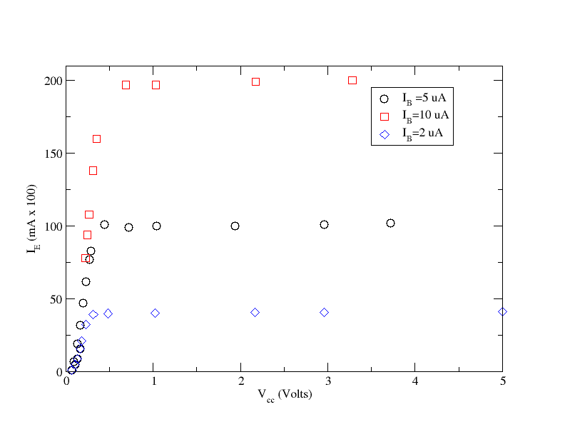
4.) Repeat the previous measurements for A. Remember to keep so the transistor doesn't burn out
| V | A | V | mV | mA |
| 1.044 | 5 | 0.094 | 7 | |
| 1.053 | 5 | 0.134 | 19 | |
| 1.026 | 5 | 0.167 | 32 | |
| 1.003 | 5 | 0.200 | 47 | |
| 1.003 | 5 | 0.234 | 62 | |
| 1.02 | 5 | 0.269 | 77 | |
| 1.0 | 5 | 0.289 | 83 | |
| 1.07 | 5 | 0.442 | 101 | |
| 1.02 | 5 | 0.721 | 99 | |
| 1.02 | 5 | 1.04 | 100 | |
| 1.02 | 5 | 1.94 | 100 | |
| 1.02 | 5 | 2.96 | 101 | |
| 1.02 | 5 | 3.72 | 102 |
| V | A | V | mV | mA |
| 0.942 | 10 | 0.227 | 78.1 | |
| 1.005 | 10 | 0.245 | 94 | |
| 0.995 | 10 | 0.267 | 108 | |
| 1.068 | 10 | 0.31 | 138 | |
| 1.005 | 10 | 0.355 | 160 | |
| 0.996 | 10 | 1.032 | 197 | |
| 1.002 | 10 | 0.688 | 197 | |
| 0.996 | 10 | 2.175 | 199 | |
| 0.994 | 10 | 3.283 | 200 | |
| 0.992 | 10 | 4.66 | 202 |
5.) Graph -vs- for each value of and above. (40 pnts)
6.) Overlay points from the transistor's data sheet on the graph in part 5.).(10 pnts)
Questions
1.)Compare your measured value of or for the transistor to the spec sheet? (10 pnts)
2.)What is for the transistor?(10 pnts)
3.)The base must always be more _________(________) than the emitter for a npn (pnp)transistor to conduct I_C.(10 pnts)
4.)For a transistor to conduct I_C the base-emitter junction must be ____forward_______ biased.(10 pnts)
5.)For a transistor to conduct I_C the collector-base junction must be ______reverse_____ biased.(10 pnts)


